- Joined
- Apr 7, 2014
- Messages
- 866
When I was learning how to sharpen and getting used to the vernacular, I found that visual diagrams were the most helpful method to learn by. However, unfortunately at the time, they were used sparingly and only when absolutely needed. Over the past few months I've been doing the same for other people just starting out, but I've decided to consolidate them here so that I can just link to it when someone has a question it can answer. If you have anything to add (or correct, since this might be a bit rushed before I'm out the door today), please feel free to do so. So without further ado, here were some of the first questions I had and how I believe they're best visualized:
What is DPS? Inclusive?
DPS stands for degrees per side. So an edge angle of 15 DPS translates to 30 degrees inclusive, as shown in the following image:

What happens when I sharpen at an angle higher than what it's currently at?
Essentially, what you'd be doing is grinding in a secondary bevel (you might have previously heard of a microbevel, which happens to be a secondary bevel so small it's difficult or impossible to see with the naked eye, typically done to increase durability). You're hitting the apex (the very edge of) the edge, which is a good thing, but not the entire bevel. This can be a good thing if you're just applying a microbevel or something along those lines, but typically you want to match the entire bevel.
So, this is what it looks like when you sharpen at a higher angle:

What happens when I sharpen at an angle lower than what it's currently at?
You'd be doing the opposite of that - you're hitting too much of the shoulder without touching the actual apex of the edge. Unlike the previous example, which at least hits the apex, this time it all it does is grind away at the shoulders without actually increasing sharpness. This can be a good thing if you'e trying to thin out the edge, but typically you want to match the entire bevel.
So, this is what happens when you sharpen at a lower angle:

Alright, so I should match the bevel. What happens when I sharpen at the same angle?
What you're aiming for here is to hit the entire bevel, not just one side or the other. That way, you're keeping the angle consistent and even.
So, this is what happens when you sharpen at the same angle:

What is the Sharpie trick?
These diagrams aside, it can be difficult to see this happening in real life. Some people use a jeweler's loupe or similar types of magnification. A simpler way of doing this is to color the bevel with a Sharpie, sharpen for a few swipes, and see where the Sharpie is ground off (not my photo, but I reference it often - if someone knows whose it is, please let me know so I can credit them):
- Red ink: using too high an angle and, as a result, only removing metal (and the ink) closer to the apex.
- Green ink: using too low an angle and, as a result, only removing metal (and the ink) closer to the shoulder of the bevel.
- Instead, you should be removing ink from the entire bevel, so after a couple passes, the ink should be completely removed from the bevel.
Hey, why the green line in that last image of sharpening at the same angle?
That is to show that as you sharpen, you grind into thicker and thicker metal, which is something to account for throughout the lifetime of the knife. It's also partly why people like to sharpen as thin as possible before the edge gets too fragile. As the edge dulls, acute angles will last longer than obtuse angles (barring material failure, e.g., chipping) since there is less material behind the edge to get in the way.
For example, at the same level of recession into the material, T2 is smaller than T1, maintaining a higher level of cutting ability:
Also, why do my bevels appear different between knives even at the same angles?
Again, it has to do with the thickness. A little trigonometry will show this:
These two bevels are on two different blades, the top being thicker and the bottom being thinner. Now, the heights (H1 and H2) are equal. However, being from a thinner blade, W2 is smaller than W1. Therefore, using the Pythagorean theorem (a^2 + b^2 = c^2), B1 ("B" for "bevel") is larger than B2. If we want the bevels to be the same size, we could also look at using SIN/COS/TAN trigonometry. If we wanted the bevels to be the same size, we'd have to reduce H1 in order to reduce B1, which would decrease the angle between B1 and W1, i.e., making the edge more obtuse.
But that's more cosmetic than anything else. Instead, sharpen at the right angle for the task at hand.
What about convex edges?
You can, of course, grind a v edge into a full convex edge and vice versa. However, you should stop and visualize what you're trying to achieve before doing so. On the left, you see how a convex edge (depending on how it's ground, of course), in green, compares to a v-edge, in black. Less material behind the edge can reduce strength but increase cutting ability. On the right, you see a similar process in grinding a v-edge into a convex edge. The exact dimensions will of course depend on your particular knife, but drawing it out like this is the first step whenever I tackle this task (credit to chiral.grolim):

Again, it depends on your knife, but it's important to show that a convex edge can actually have less material behind the edge than a v edge.
---
So, that's it for now. I might have a few other diagrams hidden somewhere, I'll take a look for them at a later time. But these are what I typically use when showing somebody how to visualize what they're doing. Hopefully this helps some of you as you're just starting out. To the more experienced sharpeners out there - and there are quite a few of them, I'm no expert - please feel free to offer corrections or input as you see fit.
Hope this helps!
What is DPS? Inclusive?
DPS stands for degrees per side. So an edge angle of 15 DPS translates to 30 degrees inclusive, as shown in the following image:
What happens when I sharpen at an angle higher than what it's currently at?
Essentially, what you'd be doing is grinding in a secondary bevel (you might have previously heard of a microbevel, which happens to be a secondary bevel so small it's difficult or impossible to see with the naked eye, typically done to increase durability). You're hitting the apex (the very edge of) the edge, which is a good thing, but not the entire bevel. This can be a good thing if you're just applying a microbevel or something along those lines, but typically you want to match the entire bevel.
So, this is what it looks like when you sharpen at a higher angle:
What happens when I sharpen at an angle lower than what it's currently at?
You'd be doing the opposite of that - you're hitting too much of the shoulder without touching the actual apex of the edge. Unlike the previous example, which at least hits the apex, this time it all it does is grind away at the shoulders without actually increasing sharpness. This can be a good thing if you'e trying to thin out the edge, but typically you want to match the entire bevel.
So, this is what happens when you sharpen at a lower angle:
Alright, so I should match the bevel. What happens when I sharpen at the same angle?
What you're aiming for here is to hit the entire bevel, not just one side or the other. That way, you're keeping the angle consistent and even.
So, this is what happens when you sharpen at the same angle:
What is the Sharpie trick?
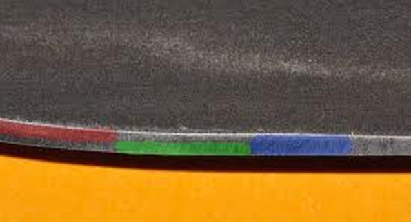
These diagrams aside, it can be difficult to see this happening in real life. Some people use a jeweler's loupe or similar types of magnification. A simpler way of doing this is to color the bevel with a Sharpie, sharpen for a few swipes, and see where the Sharpie is ground off (not my photo, but I reference it often - if someone knows whose it is, please let me know so I can credit them):
- Red ink: using too high an angle and, as a result, only removing metal (and the ink) closer to the apex.
- Green ink: using too low an angle and, as a result, only removing metal (and the ink) closer to the shoulder of the bevel.
- Instead, you should be removing ink from the entire bevel, so after a couple passes, the ink should be completely removed from the bevel.
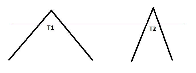
Hey, why the green line in that last image of sharpening at the same angle?
That is to show that as you sharpen, you grind into thicker and thicker metal, which is something to account for throughout the lifetime of the knife. It's also partly why people like to sharpen as thin as possible before the edge gets too fragile. As the edge dulls, acute angles will last longer than obtuse angles (barring material failure, e.g., chipping) since there is less material behind the edge to get in the way.
For example, at the same level of recession into the material, T2 is smaller than T1, maintaining a higher level of cutting ability:
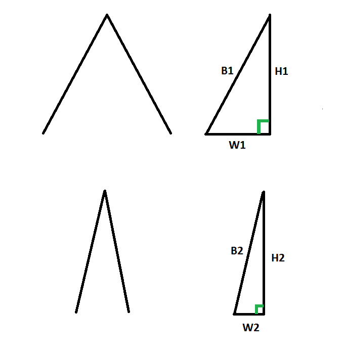
Also, why do my bevels appear different between knives even at the same angles?
Again, it has to do with the thickness. A little trigonometry will show this:
These two bevels are on two different blades, the top being thicker and the bottom being thinner. Now, the heights (H1 and H2) are equal. However, being from a thinner blade, W2 is smaller than W1. Therefore, using the Pythagorean theorem (a^2 + b^2 = c^2), B1 ("B" for "bevel") is larger than B2. If we want the bevels to be the same size, we could also look at using SIN/COS/TAN trigonometry. If we wanted the bevels to be the same size, we'd have to reduce H1 in order to reduce B1, which would decrease the angle between B1 and W1, i.e., making the edge more obtuse.
But that's more cosmetic than anything else. Instead, sharpen at the right angle for the task at hand.
What about convex edges?
You can, of course, grind a v edge into a full convex edge and vice versa. However, you should stop and visualize what you're trying to achieve before doing so. On the left, you see how a convex edge (depending on how it's ground, of course), in green, compares to a v-edge, in black. Less material behind the edge can reduce strength but increase cutting ability. On the right, you see a similar process in grinding a v-edge into a convex edge. The exact dimensions will of course depend on your particular knife, but drawing it out like this is the first step whenever I tackle this task (credit to chiral.grolim):
Again, it depends on your knife, but it's important to show that a convex edge can actually have less material behind the edge than a v edge.
---
So, that's it for now. I might have a few other diagrams hidden somewhere, I'll take a look for them at a later time. But these are what I typically use when showing somebody how to visualize what they're doing. Hopefully this helps some of you as you're just starting out. To the more experienced sharpeners out there - and there are quite a few of them, I'm no expert - please feel free to offer corrections or input as you see fit.
Hope this helps!
Last edited:


