Geometry and Kinematics of Guided-Rod Sharpeners

Oh, you mean where the long edge of the knife is not parallel to the edge of the EP's main platform? And/or not parallel to the top edge of the WEPS clamp?

Pretty much yes, so that for a given blade, there would be an angle which would give the least deviation. Or perhaps it isn't an angle, but a distance from pivot point to angle or arc
 
@brplatz: Let me get back to you about that. I'm currently really busy, but I would like to work on stuff related to that.
 
@brplatz:
Hmm... I'm busy-busy, but here are a few minor updates.

(1) I now have code that does the super-fast calculations, but only for spherical-joint sharpeners (like the WEPS-Gen2).
(2) I have various ideas about how to speed up the code for other sharpeners, but not exactly sure it would be worth it. Basically, the idea is to use nearby solutions solved earlier as a starting point to find new solutions. This would help a lot, but maybe not enough.
(3) My main problem is how to visualize the data:

Imagine a WEPS-Gen2 with a knife clamped in it. For a coordinate system, we can have the X-axis pointing parallel to the line of the blade edge, the Y-axis as pointing straight up, and the Z-axis as perpendicular to the plane of the knife. Now imagine, we choose an (x,y) coordinate for the location of the spherical joint. To satisfy our sharpening angle (for example, 15 deg per side), we can adjust the z coordinate until we hit 15 deg per side at a choosen calibration point on the knife edge. So the z coordinate is determined from the (x,y) coordinates. Now, with the pivot located at (x,y,z), we get a sharpening angle for every point on the knife edge. My problem is that this information needs 4 dimensions to easily visualize.

You can think of it as a 3-dimensional array:
Array(x,y,d) = a
x = x-coordinate of spherical joint
y = y-coordinate of spherical joint
d = distance along the knife edge for specifying a specific point.
a = sharpening angle at d on the knife edge, when the spherical joint is at coordinates (x,y,z). (Remember z is computed from (x,y).)

I tried a few things, but I did not find a way of visualizing this array that I liked. The best one I found, but am not so happy with, is to fix y, then make a 2d-contour plot where x and d vary. The user can then flip through frames of a movie, where each frame is a different choice for y. In each frame is drawn the 2d-contour plot. (Hope this makes sense...)

If I can find a nice way to visualize the results (3), then we can do something interesting. So if you or anyone has ideas, please let me know. The idea is to provide an (interactive?) visualization that then allows the user to pick what he thinks is best.

One thing I'm reluctant to do, is to blindly optimize for the user (say, minimize average deviation in sharpening angle, or maximal deviation in sharpening angle, etc.) because usually there are parts of the edge the user really cares about and other parts of the edge the user doesn't care about. So I think it is better to do a visualization rather than have a program run as a black box and return a single solution. If you have any thoughts on this, let us know.

Sincerely,
--Lagrangian
 
This is an interesting paper, but i think i see some problems with it.
I have only finished the section on the edge pro apex, but here is what is troubling me.
As a starting point, one of the conclusions that you state about the apex is that it is the horizontal displacement (pin length) that creates the inability of the apex to create a perfect dihedral angle at any other angle than 30 degrees, and the use of a universal joint would eliminate this problem, but you do not show any proof of this. I do not think this is true. Did you work this out?
 
Taking the case of a an apex modified with a universal joint as the simplest case, as the sharpening occurs on a circular plane centered on the axis of the mast, it seems to me that the function of dihedral angle should be parabolic. That is to say the the positive and negative directions in the x axis are completely arbitrary and switching them the function should remain the same, but your graphs do not seem to show this. (Yes, i know that your graphs show cases where the pin is present, if not exaggerated, but i believe the same trend should hold).
 
As a simple exercise, take a stiff piece of paper and cut it diagonally from corner to corner. When looking at the paper from the side so you view a triangle with a long flat horizontal top you can imagine this triangle to be the the bed (hypotenuse), mast (short vertical leg), and sharpening stone (long horizontal leg). If you move the point of the triangle where the stone would intersect the knife towards you or away from you (keeping the mast point still) the apparent angle seen edge-on will change equally with movement, whether forwards or backwards. Given that the apparent angle changes are in the same direction, why would the dihedral angle act differently?

Any thoughts?
-b
 
It is very interesting to note that a straight blade or plane iron can be sharpened at any angle perfectly by merely changing the angle at which it lies on the bed.
Sticky's machine seems perfect for that, as long as the stone is horizontal. If only i had a cnc. sigh.

I apologize for the multiple posts, but the forum didn't seem to like my one long one.
 
I'd like to build a sharpening system similar to the WEPS, just because it does both sides of the edge at the same time... 50% time savings right? ;):D

The difference being that my design idea is to do away with the floppy swinging arms and have two sets of parallel rods on either side of the knife holding the stones so that they can move both parallel and perpendicular to the edge which should* eliminate the angle issue.


*May or may not have any idea what I'm talking about, just know that the edge pro ain't perfect and neither is the WEPS...
 
Hi brodieb666,

Thanks for your questions and interest!

Let me see if I can echo your questions back to you, and then I'll try to answer them as clearly as I can.

In case anyone is new to this thread, let me point to the original technical report which we are discussing:
https://drive.google.com/file/d/0B8rQYhU8N9ZGSENqc2Q2MlRFbTA/
http://www.mediafire.com/download/2flrqn7po9um350/Geometry_and_Sharpening_(DRAFT_1.0beta17).zip

=======================================================================================
Questions
=======================================================================================
So I think you are asking:

---------------------------------------------------------------------------------------
(Q1) Is there a proof that if the EP-Apex used a universal joint, that then it would eliminate the small deviations in dihedral angle (when sharpening a tanto knife)?

---------------------------------------------------------------------------------------
(Q2) If the EP-Apex used a universal joint, wouldn't the set-up have mirror symmetry (reflection symmetry) through a vertical plane that went through the vertical-mast and the centerline of the main platform? If it did have such symmetry, then the graphs of dihedral-angle vs. position would have the same symmetry, but they do not. Why not?

---------------------------------------------------------------------------------------
(Q3) Let's consider the original (un-modified) EP-Apex. If there were a deviation in angle on one side of the vertical-mast, then wouldn't the deviation be identical on the reverse side? (This question is similar to Q2, but for the original EP-Apex.)


=======================================================================================
Quick Answers (without details)
=======================================================================================
To answer your three questions, let me answer twice: once super briefly but without explanation, and then again in full detail. The reason for this is that the detailed answers are quite long to explain.

---------------------------------------------------------------------------------------
Quick Answer to (Q1):
Yes, there is a proof and I did work it out. However, I did not include it in the report. This is because the target audience for the report is not a technical one. I felt that even if I did include the proof, it would be meaningless to most of the readers because either they would not read the proof, or even if they did, most would not be knowledgeable enough to either understand or challenge it. More details are below, including pointers to a (partial) proof and some visualizations that should be convincing.

---------------------------------------------------------------------------------------
Quick Answer to (Q2):
Ah, maybe some confusion here. I did not show any graphs for the EP-Apex with the modification of a universal joint. For the EP-Apex, I only showed graphs for the original EP-Apex. So I would like to make two points:

(1) The original EP-Apex is not symmetric. That is, it does not have mirror symmetry because the horizontal sliding-rod is actually on one side of the vertical-mast. When the EP-Apex is put-together, the sliding-rod could be assembled on the right-side of the vertical-mast, or assembled on the left-side of the vertical-mast. Because the EP-Apex does not have mirror symmetry, it will sharpen differently on the left-side and right-side of the main platform. More details on this are below, including a diagram that I hope makes it clear.

(2) If we modified the EP-Apex to use a universal-joint or a spherical joint then the modified-EP-Apex would have mirror symmetry. In this case, yes, we would expect the graphs of dihedral-angle vs position to have reflection symmetry. However, for a tanto-knife, it will turn out that the sharpening angle will be constant. Therefore the reflection symmetry occurs in a trivial case: all constant-valued functions have reflection symmetry.

---------------------------------------------------------------------------------------
Quick Answer to (Q3):
As mentioned in the Quick Answer to (Q2), the original EP-Apex is not symmetric (does not have mirror symmetry). More details on this are below, including a diagram that I hope makes it clear.
 
Last edited:
=======================================================================================
Long Answers (with lots of details)
=======================================================================================

---------------------------------------------------------------------------------------
Long Answer to (Q1):

Okay, I'm going to get a little technical here. Let me know if this isn't clear or doesn't make sense to you.

I'll proceed in three major stages. In the first stage, I'll try to convince you that a universal joint is _effectively_ the same as a spherical bearing. (It's not exactly the same, but it is almost the same). After you accept that, then I can discuss how a spherical bearing can grind a perfect dihedral angle on a tanto knife. To do this, I'll show some visualizations (animations), and then finally point to a (partial) proof.

- - - - - - - - - - - - - - - - - - - - - - - - - - - - - - - - - - - - - - - - - - - -
First I'll try to convince you that a universal joint is almost the same as a spherical joint. What do I mean by this? First consider a spherical-joint with a sliding-rod that goes through the center of the sphere in the joint. (These spherical-joints are also called spherical rod-ends.) The center-axis of the sliding-rod goes is a line that goes through the center of the sphere. The center of the sphere does not move (but of course the sphere rotates) because we fix the position of spherical-joint when sharpening.

So this is the key observation about the spherical joint: The center axis of the sliding rod goes through a fixed point. If you don't accept this key point, then the rest won't make sense, so let me know if this is clear or not.

Next, we'll consider a universal-joint. A universal-joint has a gimble inside. A gimble is a set of rotating joints, where the axes of the joints all intersect at a single point. I'll "prove" to you that if we used a gimble on the EP-Apex, that the center axis of the sliding-rod would always go through a fixed point (namely, the center of the gimble). If you accept the argument below, then you will see that the universal joint is very similar to a spherical joint (they both restrict the center-axis of the sliding rod to go through a fixed point).
https://en.wikipedia.org/wiki/Universal_joint
https://en.wikipedia.org/wiki/Gimble

Here is a universal-joint. Notice that all rotating joints/axes intersect at a single point in the center of the green part.
rMMjDH4.gif


Here is a gimble. Notice that like the universal joint, all rotating joints/axes intersect at a single point (namely, the center of the blue ring).
UqU1Ejk.gif


And here is a gimble that we would use in the EP-Apex. Notice that the rod can slide back and forth through the red colored sleeve. Notice that all rotating axes intersect at a single point in the center of the red sleeve.
TvQOykS.jpg


So now that we have a gimble (or universal joint), how could we prove that a sliding rod would always have an axis that goes through a single point? After all, the various joints are all rotating around. How can we guarantee that there is a fixed point, and that the sliding rod goes through that fixed point? I won't prove this in full, because I do not want to start the proof from the ground up. Instead, let me first assume a basic fact about rotations.

(F1) Fact: A rotation does not change the position of points on the axis of rotation.
Proof: Okay, I won't prove this, but this is a well-known property of rotations. Here's what it means mathematically:

Let L be a an axis of rotation, and let Theta be an angle for the rotation.
Let R(L,Theta) be a rotation around the line L by Theta degrees.
Let p be some point in 3d.
Let q = R(L,Theta)p be the result of rotating point p by the rotation R(L,Theta).

Suppose the point p is on the axis of rotation L. Then q = p because a point on the axis of rotation is unchanged by the rotation. A proof of this is in most linear algebra textbooks, or textbooks on mechanisms and robotics. (Mathematically, we say that vectors on the axis of rotation are eigenvectors of the 3x3 rotation matrix and have eigenvalues equal to one. Alternatively, we can say that points on the axis are fixed-points of the rotation function.) I think though, even without linear algebra, this should be intuitively clear.

Now suppose we have a mechanism with two rotating joints J1 and J2, where the axes of these two joints intersect at a point f. The first joint, J1, is mounted on the ground. The second joint, J2, is attached the first joint, J1. This means that if we rotate J1, it will rotate J2. But the reverse is not true; we if we rotate J2 then J1 is unaffected. (In robotics, we say J1 and J2 form a kinematic chain.)

So now we have an interesting question: Can we move point f by rotating the joints J1 and J2? The answer is no, for the following reasons. Because f is on the intersection of both axes, it is on the axis of rotation for J1. Therefore, a rotation of J1 cannot move the point f because of fact (F1). Rotating J1 will, however, affect joint J2. So the axis of rotation for J2 will "twirl" or rotate. However, by construction, J2's axis must intersect J1's axis at f, and f did not move. So, we know that f is still on J2's axis of rotation. Then if we rotate J2, f cannot move because it is on J2's axis (again by fact (F1)). Therefore, any combination of rotations around joints J1 and J2 cannot change the position of f.

Therefore, f is a fixed point of our mechanism made of joints J1 and J2.

This argument extends to mechanisms with three joints, J1, J2, J3, so long as all the axes of all the joints intersect at a single point, f, and we mount the joints sequentially (J1 mounted to the ground, J2 is mounted to J1, and J3 is mounted to J2.). (Mathematically, we can prove this by induction on the number of joints.)

So our gimble has a fixed point, f, which is the intersection of all the joint axes. Now we just need to show that our sliding-rod always goes through this fixed point. Consider this gimble mentioned earlier, the one with a sliding rod:
TvQOykS.jpg


By construction, the cylinder that goes through the red sleeve has an axis that goes through the center of the red ring. The center of the red ring is on the axis of rotation (the blue line) of joints on either side of the red ring. Furthermore, the center point of the red ring is actually the center of the entire gimble. Namely, all rotating axes intersect at the center of the red ring. Therefore, the center axis of the sliding rod always goes through a fixed point, namely the fixed point of the gimble which is at the center of the red ring.

So now, I think I have convinced you that a universal joint (and/or gimble) will constrain a sliding rod in the same way that a spherical joint constrains a sliding-rod. Namely, in both cases, the axis of the rod must go through a specified fixed point. It is in this sense that a universal-joint and a spherical-joint are effectively the same.

- - - - - - - - - - - - - - - - - - - - - - - - - - - - - - - - - - - - - - - - - - - -
Now that we have shown that a universal joint is effectively the same as a spherical joint, we can just think about spherical joints. If I can convince you that an EP-Apex with a spherical joint can grind a perfect dihedral angle on a tanto knife, then you should be convinced that the same is true for an EP-Apex with a universal joint.

So how can we prove this? Well, first let me try to convince you with two visualizations.

The first visualization is just to get you thinking along the right lines. Suppose we took an EP-Apex and modified it to use a spherical joint.
EbDN4us.png


Next, I'll try to convince you for the case where we have made the sliding arm, sharpening stone, and stone-holder infinitely thin. Have a look at the animation Figure 6.3 in the report. Or if you like, I uploaded it to YouTube here:
https://www.youtube.com/watch?v=cwT0c_Y_SBE
rs3YjBm.png


In this animation, you see a "fan" of red lines that all intersect at a single point. Imagine that this point is the center of the spherical joint (or the fixed point of the gimble). Next, imagine the red lines are possible positions of the sliding rod in an EP-Apex. As you can see, the sliding rod can make contact at every point along the edge of the dihedral angle. Therefore, for our EP-Apex with infinitely thin sliding rod and infinitely thin sharpening stone, we can sharpen a perfect dihedral angle on a tanto knife.

What about for an un-simplified EP-Apex, where the sliding-rod and the sharpening stone are not infinitely thin? Here is a visualization to show that even in this case, sharpening a perfect dihedral angle is no problem. Please see animated Figure 6.4 in the report. I've also uploaded it to YouTube here:
https://www.youtube.com/watch?v=jH3o5Ut9a08
gwX4Nmh.png


In this visualization, I show step-by-step how different positions of a guide rod (thick blue line) can sharpen a perfect dihedral angle. Although this is just an animation, each step shown can be made mathematically precise, and the whole sequence can be made into a proof. I think this animation should be convincing, without going through a mathematical proof.

- - - - - - - - - - - - - - - - - - - - - - - - - - - - - - - - - - - - - - - - - - - -
If you are _really_ interested in a proof, then you can have a look at a proof I started to write up here. It is only partial in that the proof for the part with thick sharpening stones is correct, but the way I choose to prove it is rather messy. Although it is correct, I consider it a poor choice of proof.
http://www.wickededgeusa.com/index....topic&catid=2&id=4154&limitstart=0&Itemid=271

I hope these three stages have convinced you that one can sharpen a perfect dihedral angle with an EP-Apex that has been modified to use a universal joint (or a spherical joint).

---------------------------------------------------------------------------------------
Long Answer to (Q2):
Actually, I won't answer (Q2) here. Instead, I will combine the answer with the answer for (Q3).

Briefly, though, I will say that a universal joint and a spherical joint can be arranged to have mirror symmetry (reflection symmetry). So if you did modify the EP-Apex to use a universal joint (or a spherical joint), then the entire set-up would have mirror symmetry for the long-edge of a tanto knife. But as mentioned earlier, using a universal joint (or spherical joint) would also lead to a constant dihedral angle when sharpening a tanto knife.
 
Last edited:
---------------------------------------------------------------------------------------
Long Answer to (Q3):
Okay, now we come to another interesting question. How does the asymmetry of the EP-Apex affect the sharpening angle? In the report, please have a look at animated Figure 2.3 and also animated Figure 3.11. I have uploaded them to YouTube here:

Figure 2.3.
https://www.youtube.com/watch?v=Lg3dK_n49Gw
uh4ovfB.png


Figure 3.11.
You may need to view this in full-screen HD to see all the details.
https://www.youtube.com/watch?v=xtY-TTwuT2M
dNqSlk2.png


I'll assume that you've read through the part of the report which describes Figure 3.11. So let me consider an EP-Apex with _exaggerated_ geometry, namely we make the pin too long (as shown in Figure 3.11). For simplicity, let's consider a top view and a side view.
IylQIoj.png


In panel (a), we are looking top-down onto an EP-Apex where the pin has been unnaturally lengthened. The large rectangle on the left is a top-down view of the main-platform for the EP-Apex, and the circle at the bottom-center of the rectangle represents the vertical-mast. The thin tall rectangle represents the sliding-arm. The red and black dot represents the connection between the pin and the sliding-arm. Panel (d) is a side view of (a) where we have only drawn the dihedral angle for sharpening. The lower-side of the angle represents a side-view of the knife, and the upper-side of the angle represents the sharpening stone (or sliding arm).

In panel (b), we move the sharpening stone to the left. This causes the vertical mast to perform a counter-clockwise rotation. As you can see, this pushes the marked dot closer to the knife edge. In panel (e) we have a side view that shows the counter-clockwise rotation moves the marked point horizontally closer to the knife edge. As you can see, in this case we are decreasing the included angle.

In panel (c), we move the sharpening stone to the right. Once again, this causes the vertical mast to rotate, but in the clockwise direction. The side view (f) shows that this clockwise rotation moves the marked point horizontally away from the knife edge. The resulting included angle is increased.

In our panels (d),(e), and (f) we are illustrating the case where our sharpening angle is less that 30 degrees per side. The EP-Apex has a main platform that is inclined at 30 degrees.

Suppose we try to sharpen at more than 30 degrees per side. What happens? This is illustrated in the side views (g), (h), and (i). As you can see, we get horizontal displacements that change the sharpening angle. However, now the relationship is flipped. Moving the sharpening stone to the left causes an increase in sharpening angle (not a decrease). And moving the stone to the right cases a decrease in sharpening angle (not an increase).

This flip in relationship between stone position and sharpening angle occurs at 30 degrees per side, and is clearly shown in the graphs of the report. For example, let's consider sharpening at 15 degrees per side, and 40 degrees per side. In the following images, I may have reversed which side I placed the sliding-rod on. So the side where the angle is increased (or decreased) may be reversed. However, you can see the relationship flips as one graph is increasing while the other is decreasing.

cLqyIhT.png


uockVCW.png


=====================================================================
Conclusion and Discussion
=====================================================================

I hope this helps. Sorry it was so long. As Pascal once said,"Sorry to have written you such a long letter. Had I more time, it would have been much shorter." Good explanations are short, but it takes a long time to find and refine a good explanation! My appologies for not having the time.

If you aren't convinced, or parts of the discussion are still not clear, feel free to post more questions or ask for clarification.

Sincerely,
--Lagrangian
 
Last edited:
I'd like to build a sharpening system similar to the WEPS, just because it does both sides of the edge at the same time... 50% time savings right? ;):D

The difference being that my design idea is to do away with the floppy swinging arms and have two sets of parallel rods on either side of the knife holding the stones so that they can move both parallel and perpendicular to the edge which should* eliminate the angle issue.


*May or may not have any idea what I'm talking about, just know that the edge pro ain't perfect and neither is the WEPS...

Hi Czechmate!

Not completely sure what you mean.
Maybe you can sketch a diagram on paper and then scan or photograph it for us? :)

Sincerely,
--Lagrangian
 
Hi Czechmate!

Not completely sure what you mean.
Maybe you can sketch a diagram on paper and then scan or photograph it for us? :)

Sincerely,
--Lagrangian

I was thinking of how a milling vice works, except turned on it's side with one on each side of the knife so that both edges get sharpened at once as each side would contain a sharpening stone "holder" (that's the technical term btw).

It could even be automated to take out the human element and be driven by high speed, ultra precise servo motors moving each stone/side in an alternating pattern... :D:cool:

Here's a similar vice to hopefully give an idea of what I'm talking aboot. :foot::)

image_21925.jpg
 
It is very interesting to note that a straight blade or plane iron can be sharpened at any angle perfectly by merely changing the angle at which it lies on the bed.
Sticky's machine seems perfect for that, as long as the stone is horizontal. If only i had a cnc. sigh.

I apologize for the multiple posts, but the forum didn't seem to like my one long one.

Hi brodieb666,

I just saw Sticky's sharpening rig. I like it!
Notice, though, that Sticky is using a gimble to guide the sliding rod. So for his set-up it is not necessary to keep the stone horizontal to sharpen a perfect dihedral angle on a tanto knife. If you look carefully, you will see that the center axis of the guide rod and the two axes of the joints all intersect at a fixed point (center of the white block) that does not move. So assuming perfect parts, Sticky's rig can sharpen any straight edge as a perfect dihedral whether or not the sharpening stone is horizontal or inclined.

I like the design though, and it appears to be very user friendly in how it can adjust.

I too wish I had a CNC!

Sincerely,
--Lagrangian
 
I'm back from the holidays and had a chance to do some visualizations.

So, let me mention what kind of data we're trying to visualize:

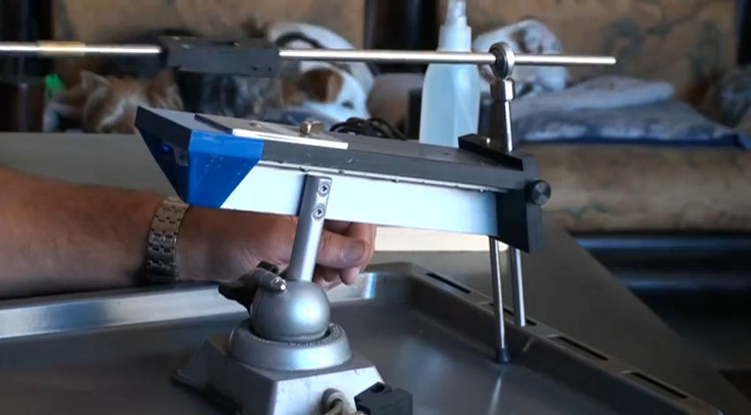
Suppose we have a Chef's knife that we want to sharpen on a WEPS-Gen2. Where should we clamp the knife to minimize the variation in sharpening angle?

What we could do, is try lots of different clamping arrangements and see how each one varies the sharpening angle, and then somehow graph or plot all the results. So what does this data look like? To find out, let us go through an example in full detail.

-------------------------------------------------------------------------
For those of you who are TL;DR, just skip to the bottom of this post to see the visualizations without any explanation. If that seems sufficiently interesting, then you can come back to read the explanations below.

-------------------------------------------------------------------------
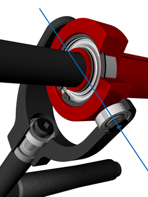
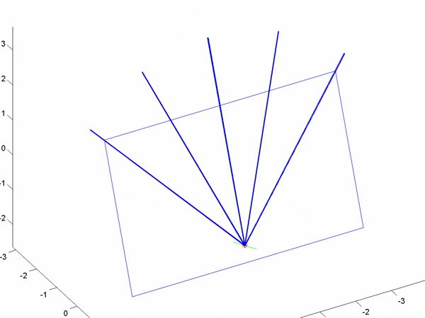
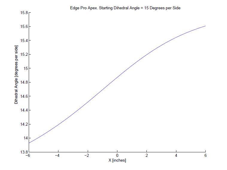
So, say I want to sharpen the chefs knife at 15 degrees per side. I'll pick a point on the knife edge that I want to be exactly 15 deg per side; this point is our _calibration point_ on the knife edge. Next, I need to try many different positions for the spherical joint in the WEPS-Gen2. I can specify the position by (x,y) coordinates where (x,y) are coordinates in the plane of the knife. The z-coordinate is perpendicular to the plane of the knife, and it is adjusted until we get 15 deg per side exactly at our calibration point. Now our knife and WEPS-Gen2 are fully set up. Finally, we get a sharpening angle for each point along the knife edge.

Given the above, we have the following:
Let x = x-coordinate of the spherical joint.
Let y = y-coordinate of the spherical joint.
Let x_knife = x-coordinate of a point on the knife edge.
Let f = sharpening angle (degrees per side) at some specific point.

So our data looks like this:

f(x,y,x_knife) = sharpening angle on the knife edge at point x_knife, when the spherical pivot is at (x,y), and z is adjusted to sharpen at 15 deg per side at our calibration point.

-------------------------------------------------------------------------
Now we have a problem: How to visualize f(x,y,x_knife)? To fully plot this, I need three inputs and one output, which would be... four dimensions. Sadly, we only live in 3 spatial dimensions, so I can't do that. In fact, I only have a computer-screen which is 2 dimensions. So how to go from 4 dimensions down to 2?

I'll try to solve this with two techniques:
(1) I'll use a contour plot.
(2) I'll use animated video so that I can use "time" as an extra dimension.

Suppose I fix the x-coordinate of the spherical joint. Then I now have a function f(y,x_knife). This would require 3 dimensions to plot. However, I can use just 2 dimensions if I use a contour plot. You may be familiar with contour plots from topographical maps.
https://en.wikipedia.org/wiki/Topographic_map
Q3Zc9u9.png


-------------------------------------------------------------------------
In a contour plot (topographic map), each contour line represents a specific height. It is kind of like having an enormous layer cake where each layer is evenly spaced. We then carve away the cake to form our mountains, valleys, and landscape. Each contour line is just a layer of icing. :) We then view everything from the top. Where the lines are closely spaced, the landscape is very steep (we cross many cake layers in a short distance). Where the lines are very widely spaced, the landscape is flat (we have to travel a long way before we get to the next layer).
-------------------------------------------------------------------------

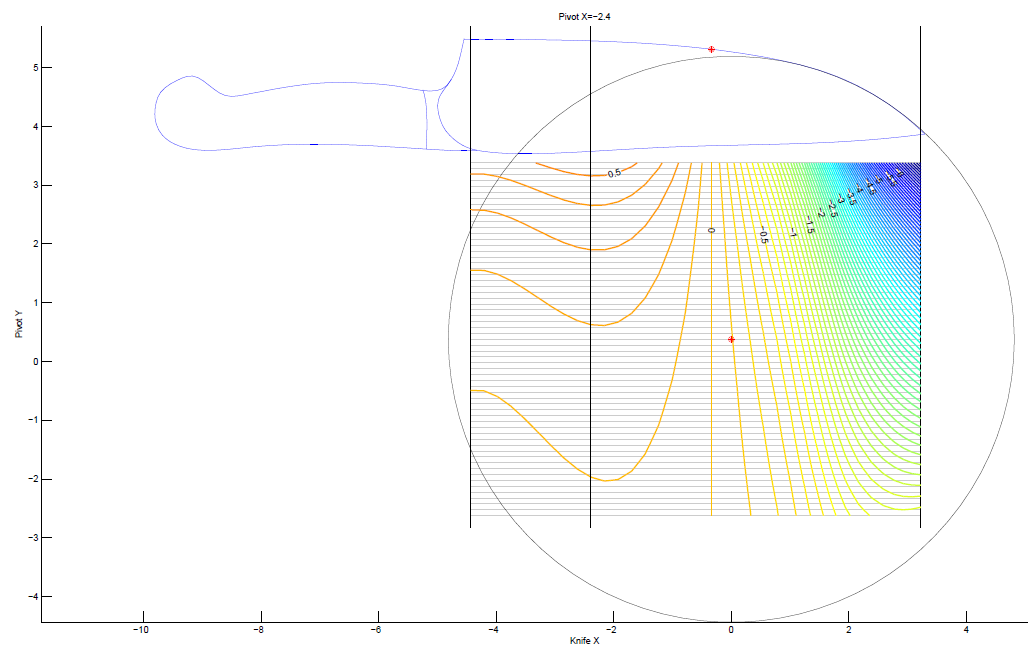
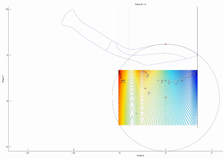
So, if we fix the x-coordinate, we get that the sharpening angle is f(y,x_knife), which we can plot as a contour map. Here's an example for our chefs knife. Don't worry; I'll explain what this picture means.
yBnvOY4.png


Let me explain all the different parts of this picture. First of all, you can see the silhouette of the chefs knife. The red point on the knife edge is our calibration point: the sharpening angle at this point will always be exactly 15 degrees per side. Suppose we want to try placing our spherical joint at coordinates x=-2.4 and y=-1. So, we first fix x=-2.4 which is represented by the black vertical line in the middle. Next we move along this vertical line until we get to y=-1. This is how we set the (x,y) position of the spherical joint of the WEPS-Gen2.

But how do we read off the sharpening angle? This is where the contour map comes in. Each of the horizontal gray lines represents a foot-path through our "landscape." From the point (x=-2.4,y=-1) in the figure, you can travel horizontally (left or right) along one of these gray lines. Each time you cross a contour, your sharpening angle has changed by 0.1 deg per side. As you walk along this gray line, your vertical altitude represents the sharpening angle for the point on the knife with the same x-coordinate (on the page, draw a vertical line until it touches the knife edge).

So in our example above, we see lots of widely spaced contours near the heel of the knife. So with our pivot at (x=-2.4,y=-1), the sharpening angle near the heel is almost constant. However near the tip of the knife, the contours get very close together! So the sharpening angle changes a lot here. So how much does the sharpening angle vary? You can find out by counting how many contours you cross as you walk along the gray line. Each time you cross a contour line, your sharpening angle (ie: "altitude") has changed by 0.1 deg per side.

-------------------------------------------------------------------------
A few additional notes: The landscape I plotted has "sea level" set to at 15 degrees per side. So the contour labeled "0" means no deviation from our target of 15 deg per side. The contours labeled "0.5" means we have increased the sharpening angle by 0.5 degrees per side, so we would be at 15+0.5 = 15.5 degrees per side. Similarly for the -0.5 contour, and so on.

Please ignore the colors in the contour plot. I'm thinking about what a good color scheme should be and learning how to set the colors in Matlab. But for now, I'm just using Matlab's default colors, which do not mean anything in this plot. I kept the colors because they are still useful for seeing the direction of contours when they get very dense.

-------------------------------------------------------------------------
Okay, so we get a specific "landscape" and the horizontal gray lines are our "foot paths". And we can walk along the foot-paths and see how many contours we cross to see how the sharpening angle varies. But this landscape was only for a specific value of x, our choice of x-coordinate for the spherical joint! We want to try many different x-coordinates for the spherical joint.

So this is where I use the technique of an animated video. I made many landscapes: one for each position of x-coordinate for the spherical joint. Each frame uses a vertical black line (the one that is moving) to represent the x-coordinate of the spherical pivot.

-------------------------------------------------------------------------
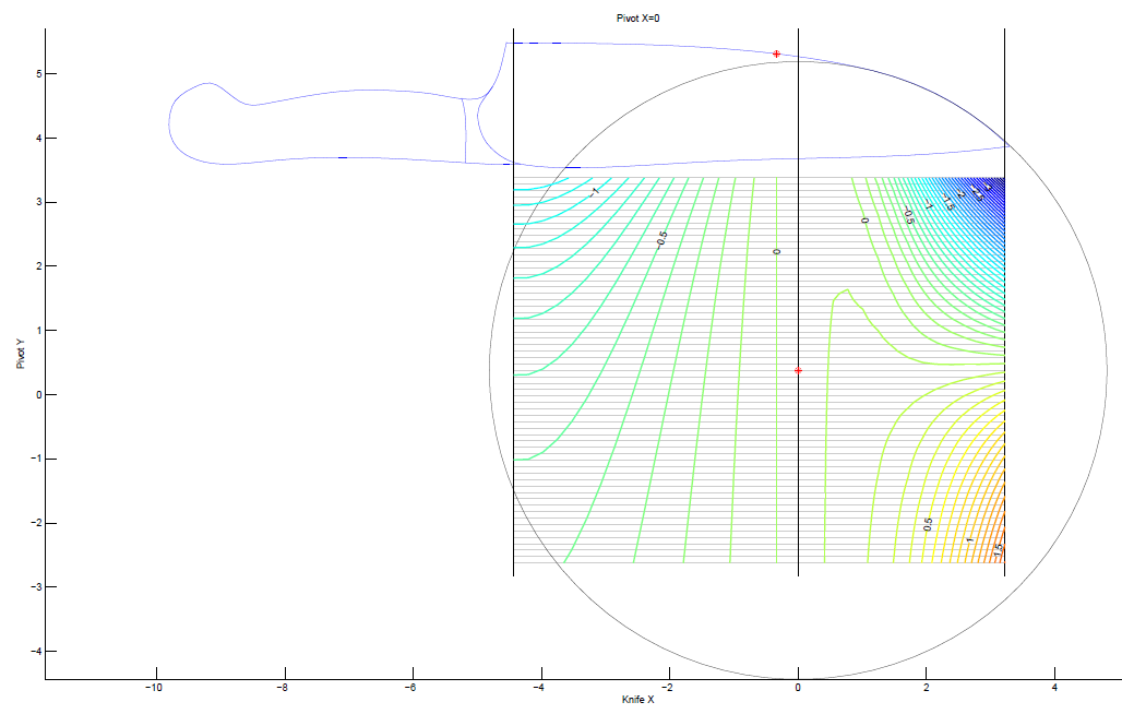
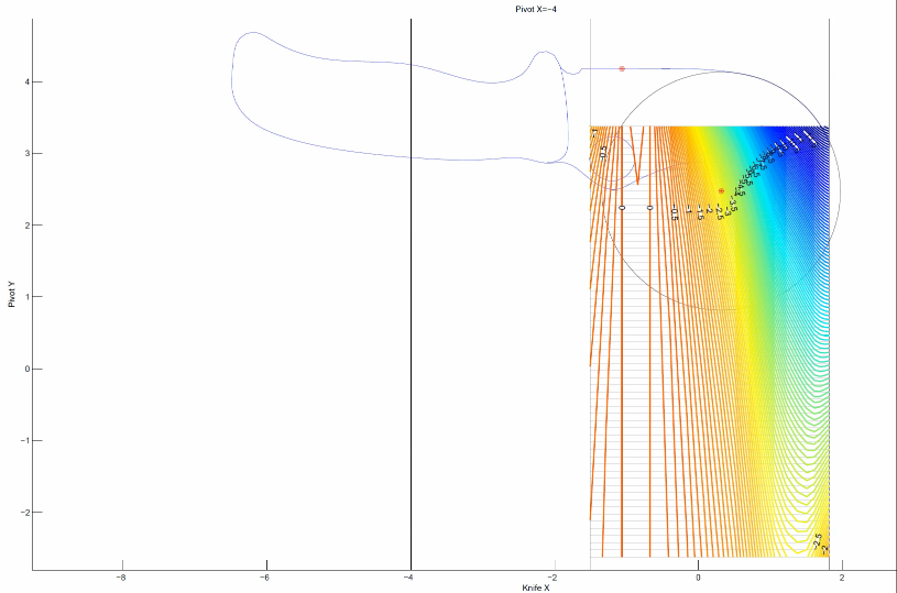
So let's work out a specific example. Do you see the red dot marked in the landscape? Suppose we want to put our spherical joint there. What we do, is go to the frame of the animation where the vertical black line goes through that point. Here is that frame.
pOHTkJ8.png


Next, the red point is on a horizontal gray line. We can walk left-and-right along the gray line. Each time we cross a contour, our sharpening angle has changed by 0.1 deg per side.

In this example, we have placed the spherical joint at the position of the red dot. When we do this, the sharpening angle near the tip of the knife is almost constant. That is, as we walk to the right along the gray line, we cross very few contour lines. We cross one, maybe two lines, which means a change of 0.2 deg per side. However, near the heel of the knife on the left, we cross many contour lines. From the plot, we can see that the sharpening angle decreases as we cross 7 contours. So our sharpening angle decreases by 0.7 deg per side.

Finally, notice the vertical contour below the calibration point. Of course this must be there! This is because we have adjusted the WEPS-Gen2 to sharpen at 15 degrees per side for every choice of (x,y) position of the spherical joint. So we will always have a vertical contour line below the calibration point, and it will have an "altitude" of zero degrees per side. That means, zero degrees per side deviation from our target angle (which is 15 deg per side).

-------------------------------------------------------------------------
So what are we looking for? We want to search all the frames for a horizontal gray line which crosses as few contours as possible, and which is also the closest to "sea level" as possible.

-------------------------------------------------------------------------
If you understood all that, congrats! Sorry if it is so complicated. :( I'm rather unsatisfied with this visualization, but it is the best I can come up with for now.

Okay, if you worked through all of that, then you deserve to see the animated videos of the contours! Here they are. I will list them twice. First is a download link to a .mp4 file. This way, you can download the video, and step through it frame-by-frame with your favorite video program (Apple Quicktime, Microsoft Media player, etc.). If you don't want to do that, you can just watch the YouTube link instead, but YouTube does not allow you to navigate frame-by-frame.
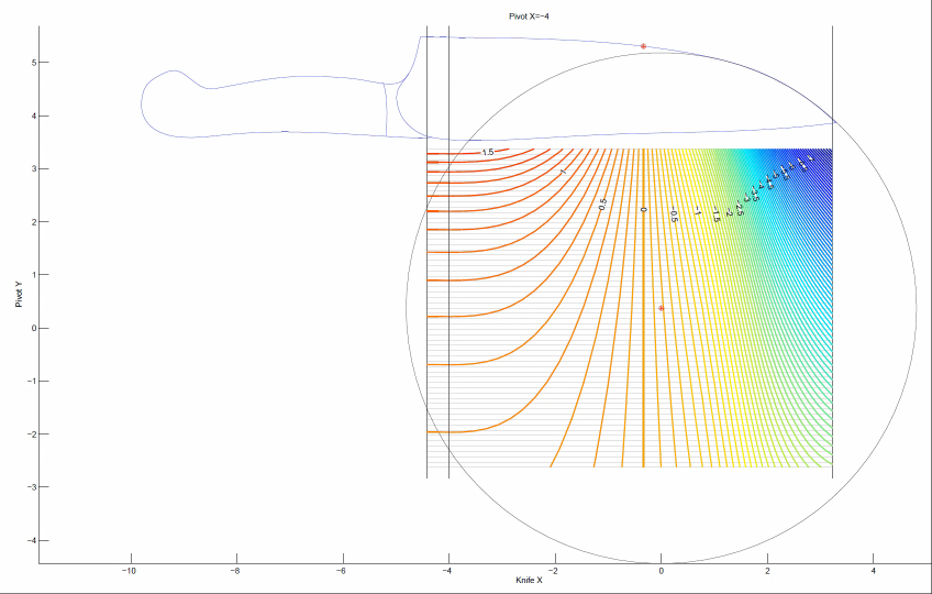
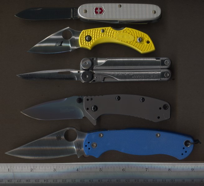
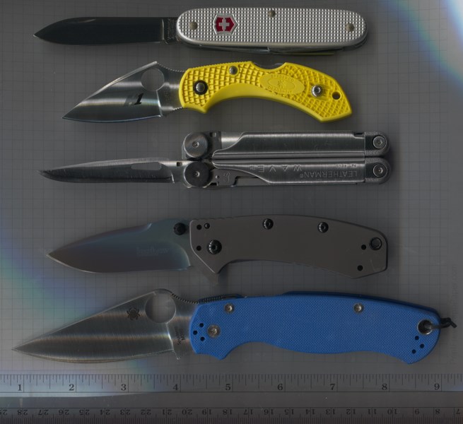
-------------------------------------------------------------------------
Chefs Knife
Coordinates are in inches.
Target sharpening angle = 15 degrees per side at the calibration point.
Contour lines every 0.1 degrees per side.
Sharpener is a WEPS-Gen2

Download:
https://drive.google.com/file/d/0B8rQYhU8N9ZGSmNzNGdlWFZhXzg/

YouTube:
https://www.youtube.com/watch?v=3x6GJQkmiJs

Preview Image:
jTmNFHP.png


-------------------------------------------------------------------------
Khukuri Knife
Coordinates are in inches.
Target sharpening angle = 10 degrees per side at the calibration point.
Contour lines every 0.1 degrees per side.
Sharpener is a WEPS-Gen2

Notes: The contour plot goes a bit crazy in the upper left corner. Please ignore these artifacts; these are caused by my software which treats +90 degrees as "the same as" -90 degrees. So when the sharpening angle goes to 90 deg per side, it can rapidly flip between +90 and -90 in the plot, which causes Matlab to draw fairly crazy contours.

Download:
https://drive.google.com/file/d/0B8rQYhU8N9ZGVXpQN2lnUjlQd1U/

YouTube:
https://www.youtube.com/watch?v=9EZndXsGyso&feature=youtu.be

Preview Image:
XgvbsuP.png


-------------------------------------------------------------------------
Spyderco LionSpy
Coordinates are in inches.
Target sharpening angle = 15 degrees per side at the calibration point.
Contour lines every 0.1 degrees per side.
Sharpener is a WEPS-Gen2

Download:
https://drive.google.com/file/d/0B8rQYhU8N9ZGc3Z0WUlGcV9IZ0U/

YouTube:
https://www.youtube.com/watch?v=Z8-Jh80wzU4&feature=youtu.be

Preview Image:
inY4cOt.png


-------------------------------------------------------------------------
That's all I have for now. If any of you can imagine or know of a better way to visualize the data, please let us know.

Sincerely,
--Lagrangian
 
Last edited:
Here is a new version. This will be the last version for quite awhile, I think.

Changes:
Expanded some of the discussion about gimbals, universal joints, and spherical joints in Chapter 3.
Re-compressed the animated contour plots with better (?) anti-aliasing settings.
Minor formatting improvements.

Geometry and Kinematics of Guided-Rod Sharpeners
Version 1.0beta17

Download:
https://drive.google.com/file/d/0B8rQYhU8N9ZGSENqc2Q2MlRFbTA/

Alternate Download:
http://www.mediafire.com/download/2flrqn7po9um350/Geometry_and_Sharpening_(DRAFT_1.0beta17).zip
 
Hi Everyone,

I'm interested in how to precisely capture the silhouette shape of a knife. After the shape has been captured, then we could use software to determine the best way to clamp a knife to get the most even sharpening angles/bevels. (For example, we could use the graphs and visualizations I posted above.)

So currently, I am experimenting with taking knife photos with a flatbed scanner, because I thought it would remove all the issues of camera alignment, perspective distortion, barrel/pincushion distortion, etc. For consumer flatbed scanners, there are two types based on the sensor: CCD (charged coupled device) and CIS (contact image sensor). From what little I have read, CCD scanners have a much larger depth-of-field, so they are better for scanning three dimensional objects (like leaves, feathers, and for us, knives).
https://en.wikipedia.org/wiki/Contact_image_sensor

I'm using a low-end CCD flatbed scanner, the Epson V33. All of the images were scanned at 600dpi, and are un-edited except for being resized to 800 pixels. Using "adjust curves" one could easily improved the contrast if needed. A clear transparency sheet was used to protect the glass platen from getting scratched by the knife blades.

Learn something every day: I was wrong about flat-bed scanners having absolutely no perspective effects! :foot: See below for details.


----------------------------------------------------------------------------------------
First I scanned a bunch of knives at once, hoping to save time. Cardboard background didn't work so well. Top to bottom, the knives are a Victorinox Pioneer Pruner (Silver), Spyderco Dragonfly Salt, Leatherman Wave, Kershaw Cryo, and a Spyderco Paramilitary 2 in M390.
FtxqNVr.jpg


----------------------------------------------------------------------------------------
Next, I tried the same thing with white graph paper as the background. Pretty reasonable, very usable, although the Swiss Army Knife is a bit dark.
5wn2UdN.jpg


----------------------------------------------------------------------------------------
At this point, I noticed something odd about the scan of the Blue Paramilitary 2: It is not a pure side view of the knife! You can actually see the top of the knife. So I tried scanning just Blue PM2 at several different positions in my scanner.


I'm using my flatbed scanner in "landscape" layout, and the scanner head is a vertical line that moves from right to left.


First, bottom of the landscape. You can see the top of the knife.
HsPLBz6.jpg


Next, mid way between top and bottom of the landscape. Looks good! Pretty much a dead-on side view.
xot5Zk8.jpg


Top of the landscape. You can see the bottom of the knife.
wj0cJb5.jpg


That was pretty interesting, so I tried the same thing going from the right to the left of the landscape.


Right side of the landscape. Looks normal for the most part.
X9Gf1mL.jpg


Mid way between left and right of the landscape. Looks normal.
Er3x75k.jpg


Left side of the landscape. Looks normal.
uTzQwhr.jpg


----------------------------------------------------------------------------------------
Conclusion:

In landscape mode, my particular scanner (Epson V33), has perspective effects going from top to bottom, but no perspective effects going from left to right. Pretty interesting! :eek:

So I think the moral of the story is:
For flat bed scanners, place your knife in the middle of the platen.

That being said, the distortion is probably too tiny to matter when we use a flatbed scanner. I suppose if you were absolutely crazy, you could scan a bunch of identical cubes (say 5mm per side) which were distributed over the entire platen, and then compare their images to measure the distortion. Personally, I'm too lazy to do that! So I'll just scan in the middle of the platen.


----------------------------------------------------------------------------------------
If any of you test your scanners, or have other ideas, then let us know.

Sincerely,
--Lagrangian
 
Last edited:
I see that this is old topic, but sharpening the knife is always actual .......BW , enough interesting reading here to make me think .....And I think Rockstead some of his knives is sharpening like this ......... larger angle at the beginning and narrow -smaller angle towards the tip of blade ? And I agree completely with this Rockstead philosophy , power of blade come from handle in tip we need more sophisticated edge .... So , look at the sketch I draw . First draw is ordinary sharpening system , the other one is modified one .
RED is blade ..............BLUE is sharpening stone...........yellow is rod guide and Green is the attachment below the blade which should enable this kind of geometry on blade .At list I think so ..............:) What do you think about this?

dzh0sx.png
 
Last edited:
Back
Top