WIP Hydraulic forge press (pic heavy)

Joined
Oct 24, 2013
Messages
906
Thanks to a great bit of information I've gained through lurking these threads as a non-member, especially eflemming and Indian George, I've taken on the the challenge of "slowly" building my own hydraulic forge press. I'm not about to go this blindly so I've ordered the appropriate literature that's been suggested by every thread I've ever read on the subject thus far;

Jim Batson's "How to Build a Hydraulic Forging Press ...

I'm not completely enthralled with knives per say, but I can appreciate the craftsmanship a great lot of you strive for. I just enjoy being around hot metal, and figured I'd just as soon give something back to the forum I've been stalking as a non-member for some time now. I will most likely not stick around as far as posting is concerned, as I don't jive with internet personalities, and personally feel the conjecture takes up a great lot of useful forge time.

My temporary list

Motor;
Leeson � 5 HP, single phase 208V/230V- $240 Fleabay

Coupling; Motor>Pump- Tractor Supply
Motor-5/8 coupling-L-090----
Pump- 1/2 coupling----L-090 ---
Flex insert-Buna-N---L-090 --- $13.40

Pump
11 GPM 2 STAGE HYD PUMP- $109.95- International hydraulic US -

4-way control valve-Std 4-Way Cntrl Valve, Model# RD2575T4ESA1--$106.15- International hydraulic US (yet to purchase)

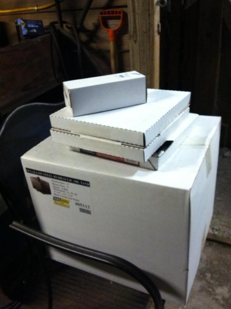
Tank 7 gal. Nortrac Steel Hydraulic Oil Tank 7 Gallon-- $99.99-Northern tool

RETURN LINE FILTER --- $20ish

Cylinder-3000psi 5 Bore x 8 stroke x 2.5 pin - $232.27 - International hydraulic US

Misc. essentials (gauge, hoses, couplings, etc)

Extend SPD- 2.2"/SEC
Retract SPD- 2.9"/SEC

Cycle SPD/Time-
Extend Time- 3.6"- SEC
Retract Time- 2.8"- SEC
Cycle Time- 6 SEC

58905 pounds cylinder push/ 29 tons

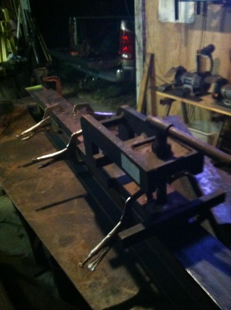
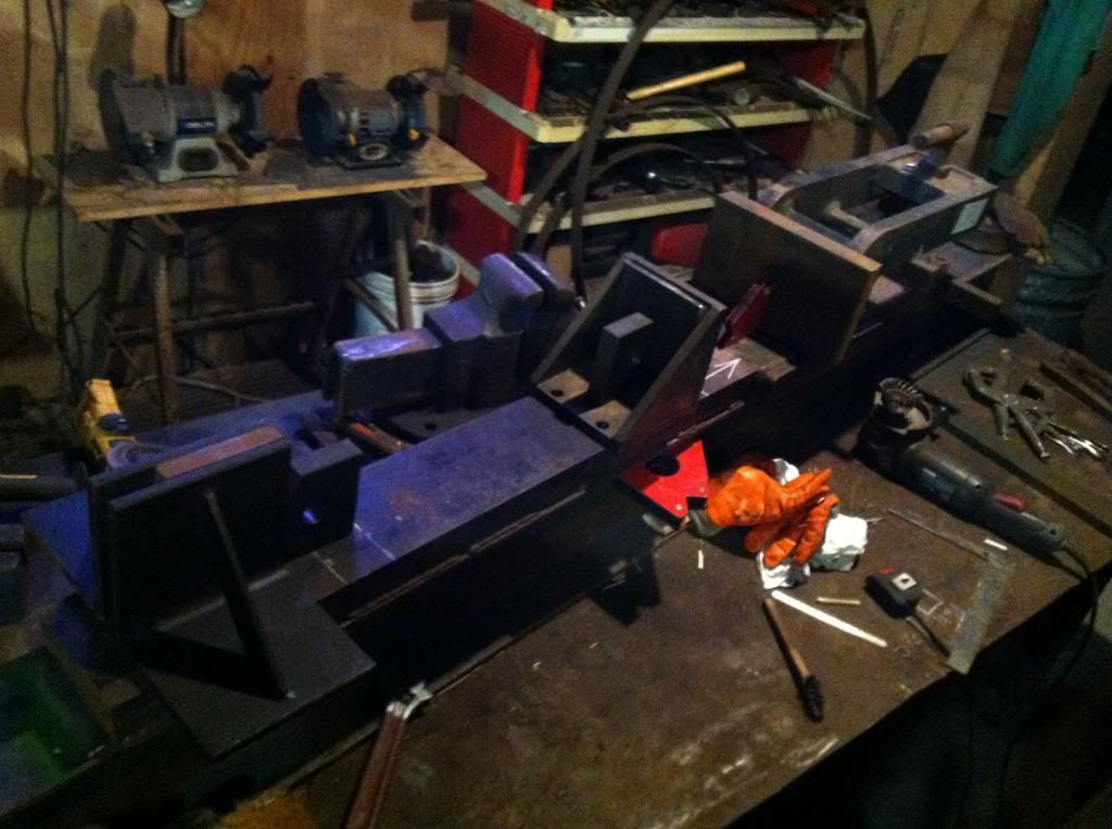
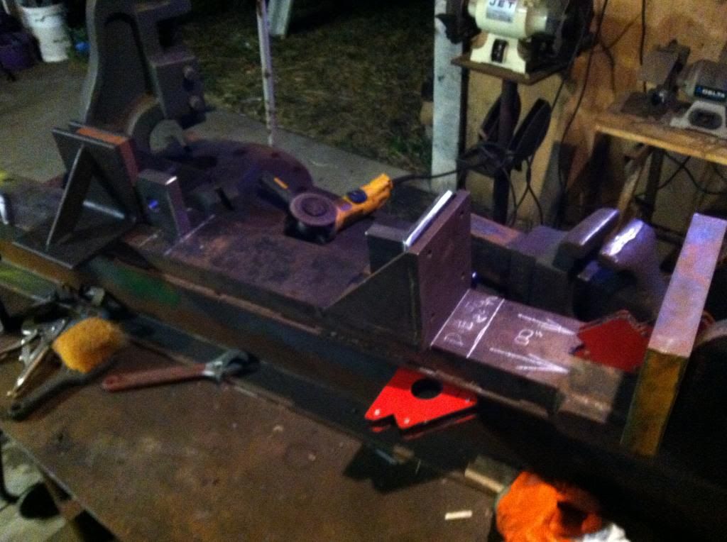
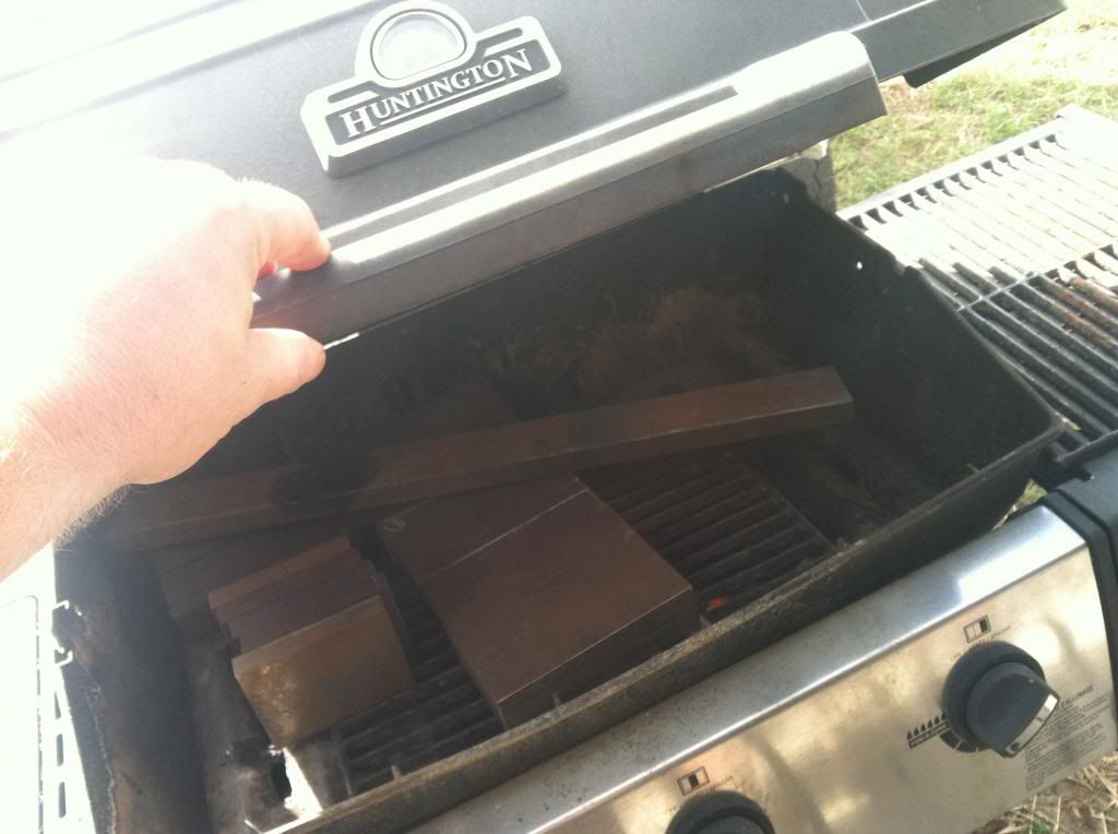
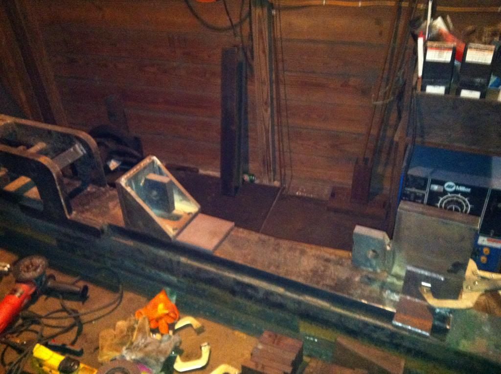
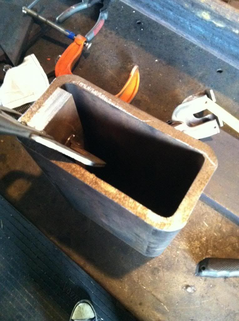
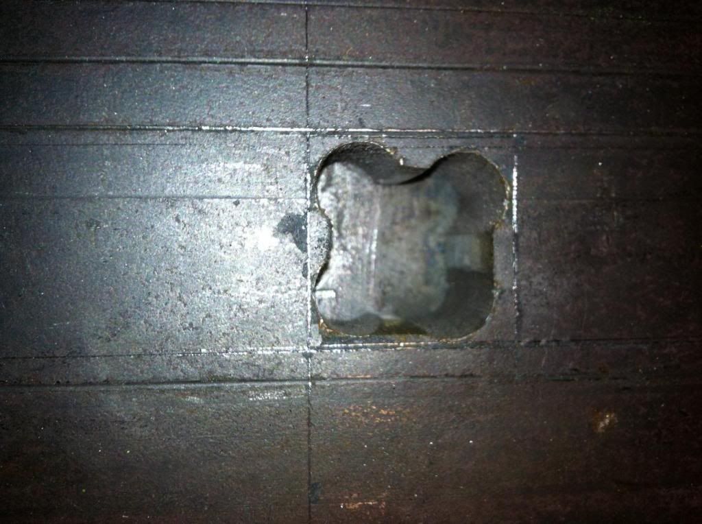
The materials that I have on hand seem to be quite conducive to the C frame build, and the C frame will also give me more access to a wider and more unique dimensions of work... My eye caught sight of forklift fork I'd purchased some time ago for a a project that never came to fruition... I think it will suffice as a fine jump off point for the build, but in the same breath I fully understand that it needs added structural rigidity.

pressframe3_zps7e4d57bc.jpg


hydraulicframe2_zps09aaa9aa.jpg


hydraulicframe_zps7db455bf.jpg


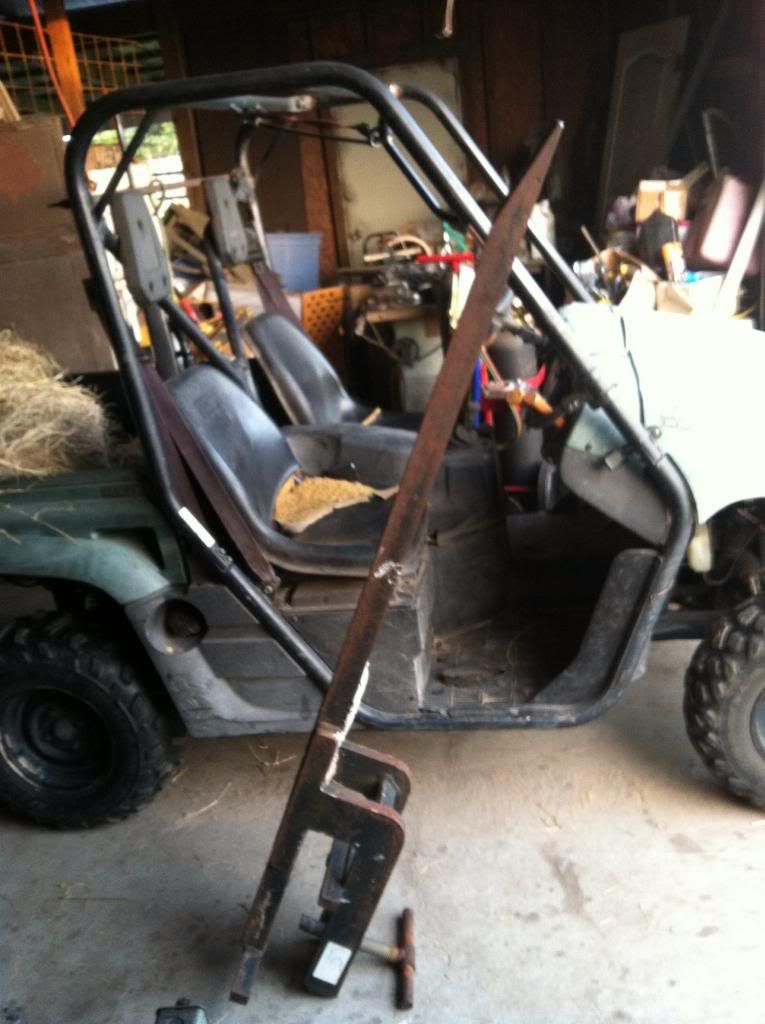
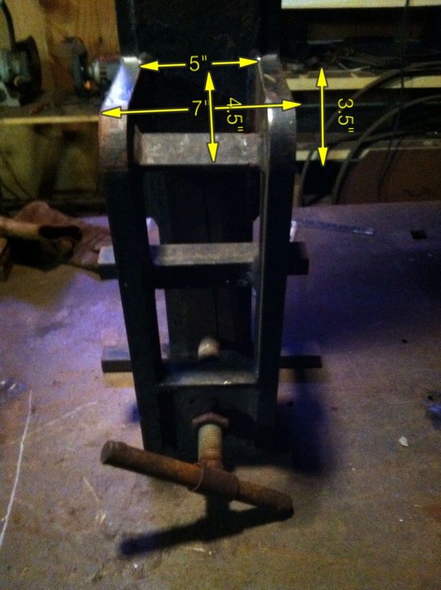
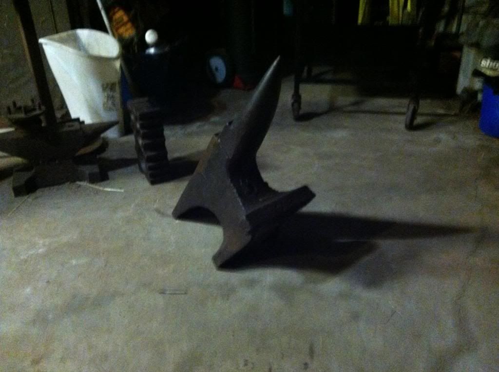
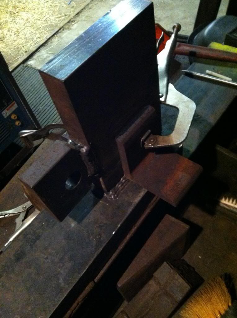
I lucked out with the purchase of this clamp on fork, at 5" wide, 2" thick, and 72" long, that webbed support portion being 1" thick plate.. Its weight is comparable to my 275 pound anvil... If it fell on a kitten, you'd never know it was a kitten if you catch my drift...

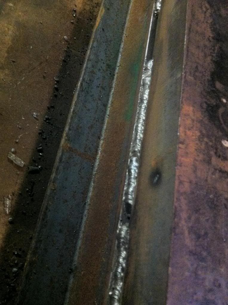
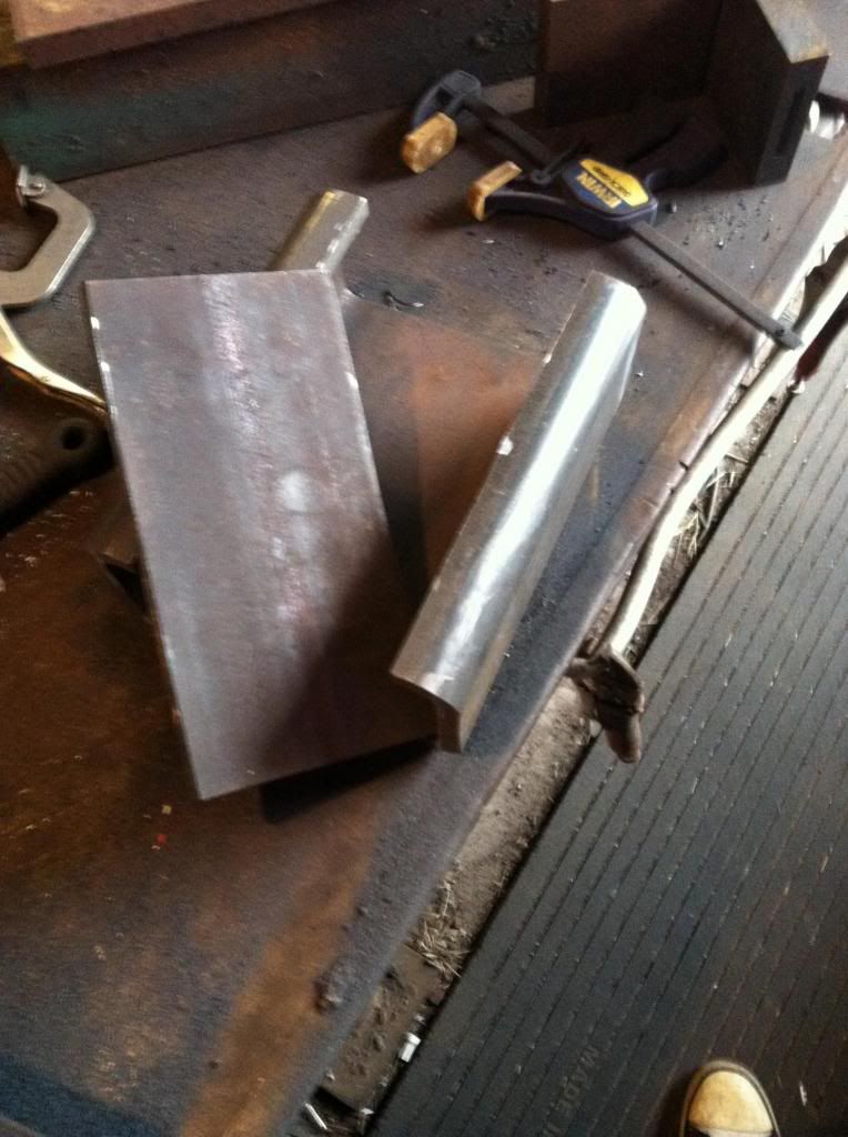
I know that these forks are most likely 4140, and are designed with bending stress in mind. However, the stress exerted, considering the application is very different than the live-load stress it would likely see in its lifty-forky day job... Preheat is definitely going to be an important factor, and though my rod of choice isn't necessary, 12018 just makes me feel better on the inside.


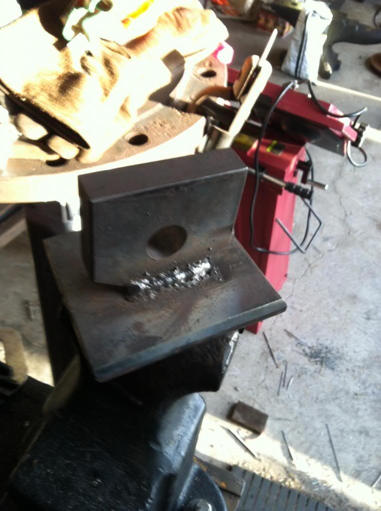
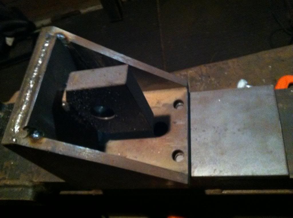
The few C frame presses I've seen are built like brick-shit-houses, but lack the material excess I've fallen upon through blind luck... The monstrosity that is this fork has to account for shortcuts elsewhere... :D

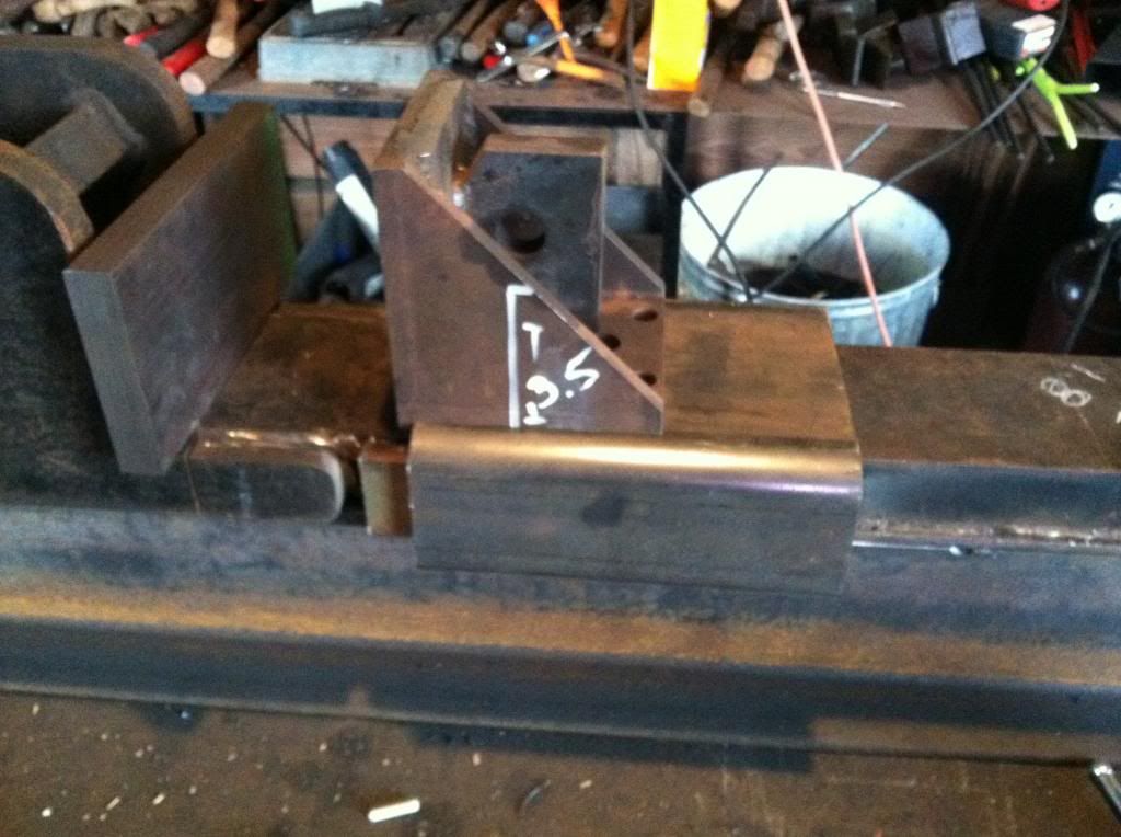
My first question for the forum would be regarding the rigidity of the frame, as I'd desire as little flex as possible. The question's more in the realm of a structural welders forte; Can I get away with say W6x12 running the full length of the press or should I up the ante???

Thanks you in advance... I'll update with sketches followed by tangible progress as time permits...
 
Seem's as if I'm a tard and put this in the wrong area... If there is a mod surfing abouts the interwebs; please move this wherever you see fit, I'm still confused at the thread mapping...
 
It seems to fit Hammer and Tongs, so I'll leave it here.

I see you picked an 11GPM pump. An 18GPS pump would be far better. Try and get the ram speed closer to 1"/sec if you can. 2.2IPS will work, but is slow.
 
I'm a bit confused on that notion, or maybe it's the way I'm conceptualizing ram speed... 1"/ a second would be faster than 2.2"/ a second?


I'm utilizing the following online calculation instruments...

http://www.baumhydraulics.com/pages.php?pageid=4

... even with the 2 stage pump @ 5.5 gpm / 5" Bore / 2.5" pin/ 8" stroke= 1.1 IPS ram speed..

I got Batson's book in the mail... I will say that the information that I've acquired through the forum corresponds directly with the information in the book. The drawings and structural safety charts are priceless. It's still a bit of a quagmire trying to figure out whether or not the W6x12 I have on hand, so I'm deciding to say screw it and just go with over-engineering frame rigidity. I've also run across a few steel machinist angle blocks I'll be using as structural elements, so I can keep the frame lined up as best as possible.
 
Last edited:
Other related news of building presses, I just scored this a few days ago, and am awaiting the arrival of a heavy ass flywheel from the midwest for retro-fit... Traded for a relatively new anvil I acquired some time back... From what I understand these presses while essentially doing the same thing are completely different when it comes to the details...

FlyPressRebuild1_zps79769774.jpg


Flypressrebuild3_zps87d5e1f5.jpg


Flypressrebuild4_zps7421742d.jpg
 
Ignore my post. I was reading the info backwards. I was thinking that it was 2.2 seconds per inch of travel....which clearly was not what you said.

A good ram sped will allow cycling the ram up and down the amount needed to move the billet ( about 1") in a second or two. The speed you quoted sounds fine. Batson's book has a great chart with cylinder size and pump size cross referencing to ram speed.
With the parts you listed you should have a good press. The one thing to remember is that the frame will have enormous stress on it.....over 40,000 pounds of it. Make it twice as heavy as you think it needs to be and you will get good results. Skimp on the main frame (normally a big I-beam) and it will flex. Welds need to be deep and strong. This is why an H frame is better strength wise, while a C frame is a bit more user friendly.
 
Happy Valentines Day update...

Got this...

photo11_zps577f29fd.jpg


Little mock up...

photo2_zpsb696558f.jpg


Stick Welded with 6011 root pass, capped with 12018M electrodes...

photo31_zpsb77b9bb9.jpg


Tadda!

photo4_zps88519098.jpg


I made some changes to the height Batson suggested... 31" AGL is mehhhhh... So I took it to 41".... Provided I don't forget them in my wife's purse, if something catastrophic happens I'd rather take one to the face than to the boys...
 
Last edited:
JB weld? I am having trouble envisioning how your press is going to look or operate but JB weld isn't designed to withstand 50,000 lbs of shear. Is that "webbing" dimensioned in the original post intended to be the die holder?
 
I think he was joking Bob, pretty obvious MIG bead in the photos, but don't feel bad, I'm having a pretty hard time following the OP's narration and particular sense of humor also. ;)
 
I think he was joking Bob, pretty obvious MIG bead in the photos, but don't feel bad, I'm having a pretty hard time following the OP's narration and particular sense of humor also. ;)

Funny, it's hard to see the welds in the photo on my phone screen- kinda looks like goop. As soon as I zoom in, then yep... Guess it is a bead.
 
The frame, and all necessary structural elements of the press are/will continue to be welded with 6011 root passes capped with 12018M.

The last thing I want is someone to read I used J.B. Weld... and repeat the process... Thanks Bob.


I'll put my humor aside for the sidebar.
 
Is that "webbing" dimensioned in the original post intended to be the die holder?

Yes, after a decent amount of reinforcement. The webbing is essentially a bucket clamp that will become a reinforced exoskeleton of a much heartier anvil block.
 
Retrofitted Flywheel to the screw press. It was a bit more complicated than I had assumed.

photo4_zpsbdf48937.jpg


..... Back to the C-frame press...

D ring shackle mounts.

photo2_zpsa4ca2125.jpg


Thanks to Chester Chicken I have a free SS hydraulic res. w/ sight glass...

photo1_zps8c3280a3.jpg


I walked up on it and scared it... It's in attack mode, protecting it's cute german girlfriend...

photo3_zpsd0e0ea60.jpg


Very raw layout... The thrust/anvil blocks are gonna be much beefier...

photo4_zps85ba5e36.jpg


photo3_zps2d66299c.jpg
 
Good looking stuff so far. Thanks for posting updates. Looking forward to seeing the rest of the progress.

Question on the welds. Curious why they stop and then continue after a small space. I am not a structural guy and what not so wondering why they dont just continue the full length of the pieces.

Haha like the anvil humor.
 
Little delayed on updates, the motor on my archaic Sears and Roebuck bandsaw took a crap. I went ahead an picked up a Harbor Freight deal as it's a real PITA breaking the last blade and not having the ability to just shoot over to home depot and pick one up.

Skip welding is intended to prevent distortion, but due to the mass of the plate I'm not too concerned with warpage. I'm hardly what one would consider to be a seasoned welder and I'm just utilizing the method because to me it parallels the way you'd tighten the lugs on a tire ensuring equal alignment through torque. I plan to preheat again and fill in the voids in the same fashion, I'm just waiting for the time/opportunity...

I've utilized this last window of time to fabricate a table for the Flypress as I've already rapped my head on that flywheel once and don't care to do it again. It's not pretty, nor is it light. I finally found something to do with this huge round steel plate. The plate itself is #200+/- and I have no idea what it came from but it's machined, hardened, and looks like a cog off a big grouser-driven vehicle. Not too bad considering that minus the legs, I used the remnant angle, solid, and square tube from past projects. The unique bracing was just something I'd come up with shooting from the hip, because the torque from the acme screw is immense. Now that I've got the press off my welding table and I can really start fabricating the components of the press.

presstable_zps6b010b3c.jpg


Anvils are always doing something dumb in the shop, they're either partaking in mustache rides, swinging from engine hoists, or ready to ambush an unsuspecting cat. I got to get them fixed or they're gonna take over the neighborhood with their shenanigans...

anvilporn_zps415c789b.jpg
 
You should send me that Fisher on top. That will cut down on the shenanigans in the shop and possibly save a passing cat!
 
For all those undertaking a build like this, the material takes for ever to prep, and grinding eats away a nice chunk of that time. Another tip I stole from youtube, which might be a bit cliché in the world of the welder, “Preheating isn’t cheating…” I used all the plate I had on hand, divided into two, heated it up and laid it on the press frame/plate, and worked them in shifts... this brought the frame/ plate up to 175 degrees for preheat, and also provided me the means for post heat, as I have no kaowool on hand for insulation.

photo14_zpsb0c925d8.jpg


I don’t know what the preheat specs are for 1.5” plate, but I assume the hotter the better… the 6011 went down like butter…

photo34_zpsbd30cdb4.jpg


Thrust block is started.

photo31_zpsfc1cbaf2.jpg


Slide block started…

I’ve cheated a bit here. The gentleman that I got the flypress off of owned an entire industrial wing full of all kinds of goodies. He gave me a great deal on some steel machinist angle blocks 4/$20. I made sure they had welds, as ductile/cast iron would have been useless. One of these blocks was drilled and matched up perfectly with the slide forklift plate, a half-inch lip overhang on each side. This block really made what I thought was going to be one of the more challenging parts of the build easier than expected, as it took a lot of work out of alignment. All this heat input through laying weld beads, even the thick stuff has the propensity to go cattywampus. I’m actually impressed with my off-center self for creating something so spot on.

Just welded the shackle mount to ½” plate and slid the plate into the angle, then welded the plate to the angle…

photo15_zps1194eaed.jpg


photo43_zps55d54b34.jpg


D-ring shackles are 4” on center proximal to the frames 2” plate leaving more than ample room for the cylinder/slide plate.

photo23_zpsf8a85eac.jpg


photo35_zps0a2d5923.jpg


to be continued…
 
You should send me that Fisher on top. That will cut down on the shenanigans in the shop and possibly save a passing cat!

Vaughn! So strange that we meet again in yet another intro thread... Well... If I did that, I'd be revealing to the world where baby anvils come from. Sadly, they're not ready for that video footage. Maybe after this whole Bigfoot DNA debacle works itself out they'll be able to handle the uncanny truth....

photo22_zps855800ba.jpg


Actually, I still use the Fisher quite regularly. I've just been inviting friends over to forge, and on this particular day a buddy of mine who's in a wheelchair due to CP came over... He was quite ecstatic that I'd taken the necessary steps to include him in on the forging. It was on the ground for the day, I just put it on top of the P'haus when the day was done so the cats wouldn't piss on it... happened once before and it's not a pleasant experience when the anvil gets warm...
 
Thread Bump…

I spent quite some time figuring out how I was going to fabricate the slide portion of the press. Batson provides acceptable drawings that enable you to adjust for front-to-back and side-to side motion, but he also speaks of an acquaintance that machined a slide out of one piece of steel that needed no gib bar or bolts. This method allowed better sight of the work. I’ll be attempting to build a hybrid of the two concepts that should need no gib bar to prevent side-to-side movement, and need minimal “out of sight” track for front-to-back adjustment. If I can keep things tight to the plates spec dimensions, I should be able to make something within the realm of one piece (ish). We’ll see if my welding/flap-wheel skills are up to the task…

This huge 1/2" rectangular tubing remnant makes a perfect slide piece.

photo27_zps2be1d9bc.jpg


photo45_zpsef98a9a9.jpg


I wanted to leave a good bit of meat on it. After I slid it on, I realized I could have finagled about 1/2" more... All is well though, it sits pretty

photo51_zpse1cf56bd.jpg


Now I need to fill in the gaps with weld. Then onto the backside adjustment thingymadoodad....

photo28_zps6b819690.jpg
 
Thrust block is nearly complete. I just have to fill in the void between the clevis mount and the frame.

photo29_zps13953685.jpg


The motor and pump have arrived, along with some essential parts. I got a chance to stop by Northern Tool in Tampa on the way back from USF... Saving me some $$ on shipping. NT has the best prices on tanks and they're comparable to Surplus Center, but all this goes out the window when we start talking about shipping charges. I've picked up most of the heavy large items @ NT and will be ordering fittings and such from SC, as they seem to have the best prices when it comes to the lil' bits...

photo52_zps5ae1d593.jpg


photo47_zps35b36b15.jpg


Square holes are a PITA!!!! I drilled/chiseled most of the metal out, then burned through a half dozen bandfile bands... I wish they would last longer than 10 minutes. Anyone know a good source for quality tough sander bands? The little harbor freight tool works great while they last, they just don't get too far...

photo210_zps354acdce.jpg
 
Back
Top