#50 Little Giant Brake Pics

Joined
Dec 13, 2008
Messages
2,986
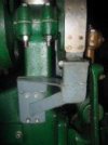
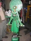
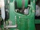
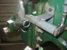
These pics were requested by a couple forum members so I thought I would do a new thread..maybe they will help someone..This brake was made by Danny Downs out of Louisville,Ky..Hes an industrial Blacksmith and a fine fellow..Poor guy has to live with a #200 Beaudry and a #200 Erie steam hammer now :rolleyes: But anyway :D Heres the pics..Also the last pic is of the toggle links he forged and made to replace the factory ones.He machines those ram guides new too. The air hose inside the spring Im guessing was there before the cage..
100_4796.jpg

100_4797.jpg

100_4802.jpg

100_4800.jpg

100_4798.jpg

100_4804.jpg
 
Now that brake looks solid, and pretty easy to understand. Thanks for the pics. I do have a few questions if you don't mind.

Is the brake connected to a hand, or foot control?

When braking for a single blow, can one have both hands free?

Did he turn the outside of the crankplate smooth, or not?

Is that leather lining the brake, and is it bonded on with barge or something?

Any idea why the hinge on top of the brake? Seems like it could be made without?

Would I be correct in assuming your hammer runs clockwise?
 
Here are some photos of the brake set up Sid uses. The material he uses is just brake banding, which is used on older tractors. The fly wheel doesn't have to be turned for them to work properly. The rough surface helps them bite better.

Dave from Diller
 

Attachments

  • brake.jpg
    brake.jpg
    24.9 KB · Views: 45
  • brake2.jpg
    brake2.jpg
    35.6 KB · Views: 47
  • brake3.jpg
    brake3.jpg
    38.8 KB · Views: 48
  • brake4.jpg
    brake4.jpg
    33.3 KB · Views: 42
I just noticed on Kentucky's hammer. The arms are forged. You'll find this on older hammers. Their kind of neat.

Dave from Diller
 
Another really cool brake. I like the simplicity of how it's combined with the clutch linkage. I may try to build one like that.

Which way is that hammer running? Does it matter with that brake setup?

Ok, one more question. Do you guys pretty much do everything, drawing out etc., with the brake hooked up? Basically it just stops the hammer from coasting, correct? Does it interfere with feathering the clutch at all?

Sorry, guess that was three questions. For five total.
 
Ok, no problem..
* The brake is connected to the foot control***If you look in the 4th pic down thats the brake control rod attached to the foot control..Both were made by Danny for adjustment and less play..
* You can have both hands free..Works very well for top tools.
* No the crank face is left "As is"
* It looks like a type of conveyor belt, yes glued on..
* I dont know why the hinge is there Salem but I really dont think it has to be..It all moves as one piece anyway..
* Yes you are correct. Clockwise
Hope this helped..
Now that brake looks solid, and pretty easy to understand. Thanks for the pics. I do have a few questions if you don't mind.

Is the brake connected to a hand, or foot control?

When braking for a single blow, can one have both hands free?

Did he turn the outside of the crankplate smooth, or not?

Is that leather lining the brake, and is it bonded on with barge or something?

Any idea why the hinge on top of the brake? Seems like it could be made without?

Would I be correct in assuming your hammer runs clockwise?
 
That does help. Thanks a bunch. Top tools would be a major reason to do this mod. I do a fair amount of blacksmithing, so I'm thinking fullering, punching, cutting, tenon forming etc. with it.
 
Regular ol' Blacksmithing is where it will make a big difference..I wa lucky enough for this to come with a couple of anvil saddles and some tools..heres a couple..Basically a hardy hole fore your hammer..Danny had an entire wall covered with these tools for his Beaudry..
100_4826.jpg

100_4827.jpg

That does help. Thanks a bunch. Top tools would be a major reason to do this mod. I do a fair amount of blacksmithing, so I'm thinking fullering, punching, cutting, tenon forming etc. with it.
 
Last edited:
VERY VERY COOL!!! THANK YOU FOR SHARING!!! :thumbup: :cool: :)

I have thought a lot about adding a brake to my hammers, but never have. I had read some folks say you need to at least grind the flywheel smooth with a grinder, if not go so far as to turn it smooth on a lathe. The idea of leaving it as cast sure sounds a lot easier. ;) :D

Kentucky, that fella sure built the brake hell for stout! :thumbup: Very nice work on that.

Dave- I know beggars can't be choosers, but any chance you could please post those pics at a higher resolution? They are really clear as thumbnails, but when I click on them, they are so grainy it's hard to make out any detail. I have Sid and Kari's video and love their rebuild process, so I'd sure like to get a better look at the brake system they prefer. Thanks Dave! :)
 
Sure thing Nick, I was worried about that when I posted them. I'll slip out to the shop and a couple of better photos.

Dave from Diller
 
brake 047.jpgbrake 048.jpgbrake 050.jpg

Here they are Matt, hopefully of better quality. These aren't really grainy, my hammers just that dirty.

Also a bracket could be made to attach the fixed side to your ram guide bolts, that way it would eliminate the need to drill holes. Same goes for the off side.

Dave from Diller
 
thanks! that brake that Downs built is probably the best example ive seen, although Sids looks easier to make. Im going to get my 50 up soon, run it then decide if and what kind of brake I will use. Always love to see pics/get ideas on these hammers.
 
Back
Top