- Joined
- Dec 19, 2005
- Messages
- 326
OK, I've read every thread I can find on building an electric ht oven a couple of times and I think I've got it. Here's the overall plan and I'm hoping to get some feedback on whether it makes sense or not. I've also got a couple of questions about size. I can't imagine it not working but I'd love any input as it's not something I wanna screw up.
My main concern is the oven in the britishblades pdf uses two 13 amp, 3.1KW 240V, which seems like way overkill for a 6x4x14 oven.
From what I've read here, many people use one 14-15 amp for ovens that are bigger (hard for me to follow the ohms and length calculations though). I'm having a hard time imagining fitting 5' of element into a box that small much less 10'.
My main question is this: I'm roughly planning on an oven size of 4x4x15” or 18”. Is one 240 Vac, 13 Amps, 3120 Watts element enough power for 18” or even 15"? I have no problem keeping it small or even going smaller but I'd really like to keep it to one SSR and one heating element if possible for simplicity, but I'll go with two if that's what it takes to make it right.
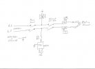
Below is my understanding of how the overall thing works. If anybody that knows about these things could give me some feedback on whether I've got it right I'd really appreciate it.
High Temperature Thermocouple for Kiln: Starting at: $26.95 Model: TC-K-KLN (borrowing this from my gas forge for now)
Product Description: This thermocouple is for kilns used for firing ceramics as it has the highest temperature rating for a K type thermocouple. It is designed for operating continuously at 2300 °F (1300 °C), or the cone 6-temperature.
Which connects to PID :
Universal 1/32 DIN PID Temperature Controller $36.95 Model: SYL-1512A (also from my gas forge update to programmable later if needed/wanted)
Power supply voltage rating 85~260VAC/50~60Hz -or- 85-360 VDC
Output mode (Relay contact: 3A at 240 VAC) (SSR: 8VDC, 40 mA)
Which connects to and controls the SSR with an 8VDC signal:
New Solid State Relay SSR-25DA 25A /250V 3-32VDC (on it's way)
(very cheap off ebay. Should I be worried enough to get a second as backup?)
Which turns one leg of the heating element off and on :
#7103: 240 Vac Kanthal Heating Element - 2300 °F Max $34.00
Material: Kanthal A1 Wire
Maximum Temperature: 2300°F
Power: 240 Vac, 13 Amps, 3120 Watts
Wire Size: .046", (17 AWG)
Unstretched Length: 41"
Minimum Operational (Stretched) Length: 60"
Maximum Stretched Lenght: 140"
Coil Outer Diameter: .280"
Pig Tail Length: 1-1/4"
OR:
Resistance wire, Kanthal A-1, 16 ga, 50ft $25
from ebay description: To make a 3400w element for use with 230v you will need about 50ft
I don't care about saving $9 or going through the extra step of winding it myself, I'm just trying to figure out if one's better than the other.
Misc stuff:
I plan on running the PID and SSR cooling fan from a 110 outlet and plugging the heating element into an outlet with a dedicated breaker box right next to it so I can completely kill the power to the elements when putting blades in and out without risk of shock, but keep the PID and fan running.
Grounding all matal boxes and skin of oven including door to 220 ground.
Is there a problem with the element being at minimal operational length? Or is it fine as long as I can keep the coils from touching?
Oh yeah, I'm using 2.5 inch brick with isowool between the brick and the steel skin. I'm adding the isowool cause I have a bunch left over from when I built my gas forge.
Sorry so rambling and thanks for any input.
Mike
My main concern is the oven in the britishblades pdf uses two 13 amp, 3.1KW 240V, which seems like way overkill for a 6x4x14 oven.
From what I've read here, many people use one 14-15 amp for ovens that are bigger (hard for me to follow the ohms and length calculations though). I'm having a hard time imagining fitting 5' of element into a box that small much less 10'.
My main question is this: I'm roughly planning on an oven size of 4x4x15” or 18”. Is one 240 Vac, 13 Amps, 3120 Watts element enough power for 18” or even 15"? I have no problem keeping it small or even going smaller but I'd really like to keep it to one SSR and one heating element if possible for simplicity, but I'll go with two if that's what it takes to make it right.
Below is my understanding of how the overall thing works. If anybody that knows about these things could give me some feedback on whether I've got it right I'd really appreciate it.
High Temperature Thermocouple for Kiln: Starting at: $26.95 Model: TC-K-KLN (borrowing this from my gas forge for now)
Product Description: This thermocouple is for kilns used for firing ceramics as it has the highest temperature rating for a K type thermocouple. It is designed for operating continuously at 2300 °F (1300 °C), or the cone 6-temperature.
Which connects to PID :
Universal 1/32 DIN PID Temperature Controller $36.95 Model: SYL-1512A (also from my gas forge update to programmable later if needed/wanted)
Power supply voltage rating 85~260VAC/50~60Hz -or- 85-360 VDC
Output mode (Relay contact: 3A at 240 VAC) (SSR: 8VDC, 40 mA)
Which connects to and controls the SSR with an 8VDC signal:
New Solid State Relay SSR-25DA 25A /250V 3-32VDC (on it's way)
(very cheap off ebay. Should I be worried enough to get a second as backup?)
Which turns one leg of the heating element off and on :
#7103: 240 Vac Kanthal Heating Element - 2300 °F Max $34.00
Material: Kanthal A1 Wire
Maximum Temperature: 2300°F
Power: 240 Vac, 13 Amps, 3120 Watts
Wire Size: .046", (17 AWG)
Unstretched Length: 41"
Minimum Operational (Stretched) Length: 60"
Maximum Stretched Lenght: 140"
Coil Outer Diameter: .280"
Pig Tail Length: 1-1/4"
OR:
Resistance wire, Kanthal A-1, 16 ga, 50ft $25
from ebay description: To make a 3400w element for use with 230v you will need about 50ft
I don't care about saving $9 or going through the extra step of winding it myself, I'm just trying to figure out if one's better than the other.
Misc stuff:
I plan on running the PID and SSR cooling fan from a 110 outlet and plugging the heating element into an outlet with a dedicated breaker box right next to it so I can completely kill the power to the elements when putting blades in and out without risk of shock, but keep the PID and fan running.
Grounding all matal boxes and skin of oven including door to 220 ground.
Is there a problem with the element being at minimal operational length? Or is it fine as long as I can keep the coils from touching?
Oh yeah, I'm using 2.5 inch brick with isowool between the brick and the steel skin. I'm adding the isowool cause I have a bunch left over from when I built my gas forge.
Sorry so rambling and thanks for any input.
Mike
Last edited:
 :thumbup: