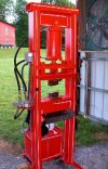
Forging press Wear plates Yes or No

Joined
Aug 13, 2022
Messages
134
Hello All
I have another thread going asking for info on my Press build and have had great help from all of you especially Ken. I wanted to repost this question as I am in the engineering stage and well just need input.
Wear plate on the forging press slide yes or no needed or not. The thought that I have gathered are they are not really needed on a home type limited use press. But at the same time, I see the valeue. Problem is when I price Aluminum bronze 954 the cost for some simple where plates exceed what I paid for my motor, control and cylinder combined.
Does anyone have pics they can share of were plate they have installed so I can see how they are mounted as to not get screws in the way.
Last question would Delrin wear blocks be an option as I have a ton of that. or would the plastic be to soft????
Thanks Jerry
 
Last edited by a moderator:
Took me a while to respond - was sorta waiting for somebody else to chime in as I seemed to hog the last thread.

I asked that same question a couple yrs ago with the response was steel is just fine for a hobby use press. Anyway, here's the thread. https://www.bladeforums.com/threads/bronze-wear-plates-required-for-forging-press.1809993/
Thanks For the reply and absolutely no you did not hog the last thread what you did was Give me directions to go. The whole point of this thread .... well done sir. and Thanks
 
So I read the post ...so where do you get bronze that don't break the bank. and again can someone post pics of how they are attached please.
Thanks Jerry
 
I don't think there is any bronze that doesn't break the bank. That's why most folks use steel wear plates. If a press is in commercial use where it's making hundreds of presses each day 5 days/week bronze "might" be worthwhile - not sure even then. For a knifemaker's use steel wear plates should be just fine. Perhaps put a tad of grease on slide, but wouldn't worry about wearing out.

Look at the Coal Iron so called 12 ton press - see the crossbar that slides up 'n down? Look at the bronze wear plates on the side with the two bolts. Those bolts screw into the end of the crossbar. Those you wish to fit fairly tight against the flats of the angle so there is little sideways play. Not tight, just sliding loose enough so the crossbar will fall under it's own weight. "IF" the steel wear plates ever give trouble you can then replace with bronze if needed. The wear plates are easy to replace anytime you wish.
 
Funny you should mention that, I was toying with the idea of simply using AR500 plate on both the frame and slide and call it good. simply replace as needed.
 
AR500 plate, or just mild steel it won't matter which - I doubt they'll ever need replacing.

Not sure what you mean by "both the frame and slide " - do you mean a long strip along the flats of the angle iron, then the plate on crossbar so you'd have AR500 sliding against AR500 steel? I see the 12 ton "H" press is of a different design than the 16 ton "H" press. Which do you plan to use? Looking more I think only the 12 ton version is suitable for an angle iron build. If the 12 ton version just take the AR500 to replace where you see the bronze wear plate on the Coal Iron "H" press.

Looks like the 16/25 ton version are using steel sliders anyway.

As a side note, since AR500 is a good bit harder than the mild steel angle iron used for frame, I might consider using mild steel for slider. You want the slider to wear faster than the frame since the slider is MUCH easier to replace than the frame. While I doubt the AR500 would cause the frame to have much wear in your lifetime when used as a hobby press - I think I might consider using mild steel rather than AR500.
 
Yes Ken exactly.
I was thinking about a say 12-inch piece on the flats (only have 10 inches of ram travel) of the angle facing in. and then on the contact points on the slide so in effect i have replaceable surfaces contacting only and I agree no need for AR500 just reg A36.
Just working out how to attach them .The ones on the angle will be held on with counter sunk screws but the one on the slider I wanted moveable so I can tighten up a few grub screws to account for wear. Ill draw up another of my stellar diags and post it for you to dee .... Let me know if I am way overthinking this.
Again, thanks for your help Ken.
 
Are you overthinking? Perhaps, but it sure is better to over think than underthink a project.

How many times each week do you think this press will be used? For a press that is used 5 days/wk, 8 to 10 hrs each day making hundreds of operation each day requires one level or build. A hobby use where the press might be used a few times a week, then sit for a week or so before more use is a different level.

For a 25 ton press the slider plate is going to need at least 1" thick. When the billet is exactly in the middle between the two vertical supports there is almost no pressure on the slider. When the pressure is applied to one side 25%-75% there can be a lot of pressure applied. This is one reason to keep keep the vertical supports as close together as possible. My "12" ton press has 8" of clearance between the vertical supports. With your 5" cylinder I might strive for 10" max?

My "12" ton press has 1/2" bronze sliders - I allowed the pressure to be on one side - don't remember why and the slider plates actually bent a tad (I might have been testing at 16 ton?). Not much, maybe 1/32" (or less). Just enough to tell it. I turned them over so the would be flat with the bolts tightened.

I'll hold off any more comments until I see your drawings.

feel free to contact me via email at sailingtoo at gmail.com

Later
 
Thanks for your comment.
as you again answered an important question. I was shooting for 15 inches between uprights. Figuring what I would lose in the slider I would be left with 12 inches of useable space. But my dilemma was the wider I go the more deflection I may get especially if I am off centered a bit. so I am going to scale that back to 10 Mabee 11 inches max between the uprights.
Right now, I am machining a couple parts I will draw up my intentions when I get those parts done and can send a pic.
Once again thanks for your help
Jerry
 
If you can find a good pic of a Claiborne Press it might give you some ideas of dimensions/ratios on an H- frame that worked nicely for its day. RIP Bowie
 
I found a photo of the Claiborne Press and it looks like it might have well over 12" or so between the uprights, but it does have a STRONG looking frame. Of course you're going to have a very strong frame also. The extra space between the frames will allow more working area by turning at an angle to the dies. As long as the work is in the center portion of the press the extra space isn't a problem as long as the cross bars are strong enough to prevent excessive deflection.

Thinking about it I might go for 12" or so between the uprights to have a bit more working space.
 
Here's a Bowie press:
The dies were about 5" wide IIRC. They're angled.

press.jpg  1.jpg
 
Last edited:
That's a good photo of the press for sure. Is that a 6" cylinder? Looks larger than a 5".
 
It has been a long time, Ken. That may have been a 5.5" cylinder, though I can't remember where he sourced them. I do know it was between 20-25 ton. It was a really nice press. Didn't have all the modern size for cutting feather and all that, but there's quite a few out there and people sure weren't complaining back then.

If you look closely, you'll see pinstriping. All of his presses were pinstriped. Bowie loved hotrods, especially T-buckets.
 
Fitzo, you don't have to look closely to see the pinstriping - it really stands out. I've seen a few photos of his presses and they really do standout.
 
Hello Ken
Sorry I have not been on in a bit with any progress on my press with all the help y'all have given me. I was waiting on 2 pieced to be machined to accept the cylinder yokes and pins. they came back and didn't fit so i had to re do them so I finally may have them by the end of the week so I can finally start building.
My question for today is.... when my ram is at full extension with the die plate (Minus dies) all attached what kind of gap should I leave between the bottom of the ram and the top of the bottom plate minus dies. Or do I set it up so they barely touch? Then whatever dies go in I just stop the stroke, when they hit, or the materiel will stop the downward movement for me. I just want as much rom as I can get between the dies. I hope that make sense.
 
If I get your question, the distance from die plate to die plate at full extension should be the thickness of your thinnest dies. If you use 1" thick flat dies, the gap would be 2".
 
Hello Ken
Sorry I have not been on in a bit with any progress on my press with all the help y'all have given me. I was waiting on 2 pieced to be machined to accept the cylinder yokes and pins. they came back and didn't fit so i had to re do them so I finally may have them by the end of the week so I can finally start building.
My question for today is.... when my ram is at full extension with the die plate (Minus dies) all attached what kind of gap should I leave between the bottom of the ram and the top of the bottom plate minus dies. Or do I set it up so they barely touch? Then whatever dies go in I just stop the stroke, when they hit, or the materiel will stop the downward movement for me. I just want as much rom as I can get between the dies. I hope that make sense.
Glad to get an update what your progress, I've been wondering how it was going. Looking forward to more reports - AND A DRAWING of your frame {g}

How are you handling the wearplates?
 
Back
Top