I've designed a lock and would like feedback (no prototype just drawing)

Joined
May 5, 2008
Messages
644
It's raining, I'm a bit sick, so I decided to fool around with Photoshop and think of a lock as an alternative to the axis lock.
I love the axis lock and can't wait till the patent expires so other brands can start using it to.

Those familiar with the workings of the axis lock know why it is such a good lock.
Very very sturdy lock, will not fail.
Easy to produce.
Easy to operate.
Keeps the blade closed under spring pressure (unlike frame lock)
Will compensate for wear.

I tried to think of a lock with the same attributes but didn't get much further then a twist on the axis lock. (Like Spyderco's ball bearing lock)

The downsides when compared to the axis lock is you need to keep the lock unlocked manual when opening and closing the blade and it would be less easy to produce.
The upside is it has a half stop lock (although you would have to fiddle with the lock, it's not like a slip joint with a half stop) and it compensates for wear when the blade is closed. (axis does not do this)

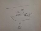
I'm not a native English speaker and I'm terrible with technical terms so I will let the pictures do the talking.
Two things to note:

- the locking bar gets thinner towards the blade as you can see on the pictures
- the locking bar locks further then the pivot. (important when blade is closed or half open)

That's a lot of text for something which probably doesn't even work, I'm not an engineer, I would like some feedback :o

Bullet lock June 28 2014

JamVlQ7.jpg

WXkVj5A.jpg

PKSh169.jpg
 
What purpose do you envision this lock to be used for? For me, having to manually open the lock to deploy the blade would make it ill suited for tactical use...don't need an extra step under duress. But for utility cutting this could be a winner...if the engineering is sound. Still, not sure the advantage over an axis lock. I guess the compensation for wear would be beneficial over time...if you knife wears sufficiently for this to be an issue? Like the innovation, just not sure the practical use.
 
You might want to check out CRKT's GW Hawk D.O.G. (Deadbolt Over Grabstep) knife. The Deadbolt Over Grabstep lock is very similar to what you have designed. It's a cool knife.
 
What purpose do you envision this lock to be used for? For me, having to manually open the lock to deploy the blade would make it ill suited for tactical use...don't need an extra step under duress. But for utility cutting this could be a winner...if the engineering is sound. Still, not sure the advantage over an axis lock. I guess the compensation for wear would be beneficial over time...if you knife wears sufficiently for this to be an issue? Like the innovation, just not sure the practical use.
I think you could open a knife with this lock just as fast as with an axis lock knife. With an axis lock you also keep the lock open when you use the thumbstud otherwise you would have friction.

What I meant was with an axis lock you have the ability to unlock, open the blade just a bit, then let go of the lock and open the blade further. That's not possible with this lock.

This lock also could have a button on top of the handle (and sides) which axis can not.


The only real upside to the axis is it compensates for wear when closed (not a real life issue with axis) and it also keeps the blade firmer in place when closed. This lock is just as strong when the blade is closed or open, the axis lock is not. More like a theoretical advantage really, never heard of people having issues with the axis lock not keeping their blade closed.
 
Thank you so much for the courteous and respectful way you have asked for feedback on your design! :thumbup:

As we say in America, you are a "class act."
 
Man! I think this would work!
A similar lock idea was in my head for quite some time! But, that's where it stayed. I was going to call it the Plungelock!
Go, Man!
rolf
 
You might want to check out CRKT's GW Hawk D.O.G. (Deadbolt Over Grabstep) knife. The Deadbolt Over Grabstep lock is very similar to what you have designed. It's a cool knife.

Watching a Youtube video now. That was a good call.

It looks the same as the design I made for locking the blade when open. Although I can't see if it is made to compensate for wear, could very well be the cut out on the blade (and the bar) is completely straight.

The bar in my drawings can also rotate to minimize wear.

The main difference is that lock does not keep the blade in place when the knife is closed. (because the locking bar should go beyond the pivot for that to work. if that even works, I just made a drawing :p)
I think it uses a ball like a frame lock to keep the blade closed.
 
I like the lock idea, it is innovative. And I especially like the pink knife handle!
 
Make sure you radius the tang butt so that the tang slides cleanly over the lock. As drawn, your butt tang is squarish, which will force the lock bar up -- or jam -- when closing.

The DOG lock also has a ramp ground into the tang so that there is no vertical blade play and future wear is managed.
 
Make sure you radius the tang butt so that the tang slides cleanly over the lock. As drawn, your butt tang is squarish, which will force the lock bar up -- or jam -- when closing.

The DOG lock also has a ramp ground into the tang so that there is no vertical blade play and future wear is managed.

I thought about that but decided to go with lock-up when the blade is half open.
Reason for that is I thought it would jam anyway even with a rounded butt.

Thanks for the info on the DOG lock so it is the same as my idea only it doesn't lock the blade when closed.

After watching a video of a DOG lock knife I can see I've been very generous with my lock surfaces. It could probably be re-designed so it does not jam as you suggested. (more room to fiddle about with butt geometry)
A real engineer would make a prototype after that and see what works best I would think.
 
Well first off, let me agree with marcinek! Also, please keep in mind I went to bed at about six this morning, ilistrating isn't coming easily at the moment haha. Along with that, I'm fifteen, some of this very well could be incorrect. :o

The major problem I see is highlighted in #1 & #2 - the red represents where the most pressure would be held when any up/down pressure is applied to the blade. The main worry would be the materla holding your locking rod busting. Assuming we're talking a ~125" peice of stock that's like .750 long, heat treated steel, it would take a massive amount of force to break the bar itself. That would rule out some handle materials I would guess. The little peice you actually pull back on to disengage the lock, would also leave an open space meaing less martial around the highest stress part of the knife.

So #3 & #4 are basically diagrams of an axis lock. The beauty off the axis lock is due to the lock face being slanted up, it can compensate for wear, and when downward force is applied to the spine the omega spring forces the lock bar up into the blade, wedging it against the stop pin, making it lock harder...I tried to make a diagram but it wasn't happening haha.

(Click to enlarge - zoom is your friend)
image.jpg

My only suggestion is to add a stop pin for the open position. Right now as is, whether the force is being applied to the spine or the edge, your locking mechanism is taking all of the stress. If you add a stop pin, only pressure on the spine will apply force to the lock, the 90 percent of force that is applied to your cutting edge during normal use will be taken up by your stop pin. Which not only improves strength, but the longevity of the mechanism.

Thanks for getting me thinkin' man, was kinda groggy but this was fun to think about!! There are probably some flaws in my logic here...I'd love to hear what I messed up. :D
 

Attachments

  • image.jpg
    image.jpg
    24.3 KB · Views: 34
It's so similar to the Blackie Collins bolt action, that I'd make sure to clear it with his family, heirs, whatever. Maybe some patent infringement can be seen in the drawings.
 
Reminds me a bit of the CS Pocket Bushman lock as well, though not exactly the same.

Looking forward to see what you do with this.
 
Well first off, let me agree with marcinek! Also, please keep in mind I went to bed at about six this morning, ilistrating isn't coming easily at the moment haha. Along with that, I'm fifteen, some of this very well could be incorrect. :o

The major problem I see is highlighted in #1 & #2 - the red represents where the most pressure would be held when any up/down pressure is applied to the blade. The main worry would be the materla holding your locking rod busting. Assuming we're talking a ~125" peice of stock that's like .750 long, heat treated steel, it would take a massive amount of force to break the bar itself. That would rule out some handle materials I would guess. The little peice you actually pull back on to disengage the lock, would also leave an open space meaing less martial around the highest stress part of the knife.

So #3 & #4 are basically diagrams of an axis lock. The beauty off the axis lock is due to the lock face being slanted up, it can compensate for wear, and when downward force is applied to the spine the omega spring forces the lock bar up into the blade, wedging it against the stop pin, making it lock harder...I tried to make a diagram but it wasn't happening haha.

(Click to enlarge - zoom is your friend)
View attachment 452867

My only suggestion is to add a stop pin for the open position. Right now as is, whether the force is being applied to the spine or the edge, your locking mechanism is taking all of the stress. If you add a stop pin, only pressure on the spine will apply force to the lock, the 90 percent of force that is applied to your cutting edge during normal use will be taken up by your stop pin. Which not only improves strength, but the longevity of the mechanism.

Thanks for getting me thinkin' man, was kinda groggy but this was fun to think about!! There are probably some flaws in my logic here...I'd love to hear what I messed up. :D

Good drawings, I know exactly what you mean with your first point (#1 and 2) Thanks for the good feedback :)
The housing is a tube, the locking rod is round and can rotate to compensate for wear. (the "buttons" to operate the lock are on both sides and on top and are not fixed on the rod. the rod can rotate inside the ring with the buttons)
Anyway, maybe extending the tube much further towards the blade would help relief some of the stress. Obviously the underside of that piece of extended tube must remain open for the blade to touch the rod.


I'm not sure what you mean with your second point (#3 and 4). I also have a stop pin..?
My lock face (on the blade) is also slated up like an axis lock, same with the rod which gets thinner near the blade.

I also find this an interesting remark:
"when downward force is applied to the spine the omega spring forces the lock bar up into the blade, wedging it against the stop pin, making it lock harder."

Could you elaborate because as far as I understand, on an axis lock, the only movement the spring makes happen is horizontal. It pushes the locking bar towards the blade.
 
Thank you so much for the courteous and respectful way you have asked for feedback on your design! :thumbup:

As we say in America, you are a "class act."

C'mon, doesn't everyone here who posts stuff about new locking mechs act like this? :D
 
I used to feel the axis lock was second only to the Tri-Ad lock but I've changed my mind on that after watching the hard use test videos by Vininull on the Adamas and the ZT0550.

I believe an Axis lock might take more gradual pressure but a good sturdy framelock will handle shock better. Shocks to the Axis lock result in a deformation to the liners inducing unfixable vertical play. Granted the blade will still not close on your fingers but that knife is done.
 
Good drawings, I know exactly what you mean with your first point (#1 and 2) Thanks for the good feedback :)
The housing is a tube, the locking rod is round and can rotate to compensate for wear. (the "buttons" to operate the lock are on both sides and on top and are not fixed on the rod. the rod can rotate inside the ring with the buttons)
Anyway, maybe extending the tube much further towards the blade would help relief some of the stress. Obviously the underside of that piece of extended tube must remain open for the blade to touch the rod.


I'm not sure what you mean with your second point (#3 and 4). I also have a stop pin..?
My lock face (on the blade) is also slated up like an axis lock, same with the rod which gets thinner near the blade.

I also find this an interesting remark:
"when downward force is applied to the spine the omega spring forces the lock bar up into the blade, wedging it against the stop pin, making it lock harder."

Could you elaborate because as far as I understand, on an axis lock, the only movement the spring makes happen is horizontal. It pushes the locking bar towards the blade.

How to the "buttons" actuate the lock without being fixed?

3 and 4 are what happens when I get caught up in my thoughts and miss obvious things...sorry :o

I thought about it, and I'm not entirely sure how accurate my statement was...the omega springs are literally shaped like an omega, and exert force towards the blade and down to a certain extent. But I'm not sure that means what I'm saying is correct...
 
Reminds me of a piston lock. I opened up my SOG trident and it has a similar lock (they call it an arc actuator) except there is a release only on one side and it only pivots instead of sliding. It's had some some up and down play now for a while though.
 
Back
Top