Need help electrical wiring blower for forge

Joined
Aug 17, 2008
Messages
184
I have my forge finally ready EXCEPT for the blower. I am no electrician. I can however wire a switch and socket and simple stuff. I managed to wire the motor for my Coote's grinder and it runs ok. Switch even works :).

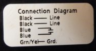
I have a blower that was recommended to me by some knifemaking folks here. I am going to show a diagram below and hope that some electrician will have pity on me and tell me how to wire it.

Black -- Line
Black -- Line

Blue --
=
Blue --

Grn/Yel -- Grnd

I can't get the equal sign to go out to the end of the dashes in the diagram. I guess it doesn't like spaces before the equal sign. Sorry for any confusion that causes.

It is 115 volt motor 50/60 hz. I understand the grnd is ground. I don't understand two lines. I thought there should be only one. The blue wires, I don't have a clue what they are for.

Thanks in advance for any help.
 
Last edited:
The blue is probably a capacitor to a start coil winding

From your description, it looks to me like:
attach the two blue together (which makes no sense to me electrically)
attach your hot to a black
attach your white to a black
ground to the ground

I have wired a bunch of motors and I've never seen two blue together like that.

Can you post a pict of this diagram and information plate. Is this a multi speed motor?
 
do the wires have any numbers on them? is there a wiring diagram on the name plate, you can check out this website it might help.

http://catalop.wegelectric.com/img/Wiring_Diagrams.pdf

the single phase motor at the bottom of this link, single voltage, reversible rotation or dual voltage, single rotation. the numbers on the wires should match the one on the diagram if the do, wire as per the diagrams.

if there are no numbers on the leads, then a ohm meter will be needed to find out which wires are the windings, if there is continuity between two leads that is one set of windings, once you do that feel free to contact me and i will do the best i can to direct you on what wire go where.

p.wildeman@sasktel.net

good luck.
 
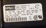
Here are the two labels from the blower I bought. Maybe this will help.

Label 1.jpg

Label 2.jpg

Thanks for any help
 
Looking at that, I think my initial post is probably mostly correct. I still don't understand the blue wire. Speed control?

BTW, a 1/40th HP blower isn't going to move much air, but I don't know how much is needed for your application.

The blower fans I have here for moving air are 1/4 HP and 1/2 HP.
 
Thanks guys. I will contact the company about a starting capacitor and wiring instructions.
 
That funny symbol for the blue wires is the electrical symbol for capacitor.
The motor is a two speed motor. The 120V line voltage goes to one of the black leads from a double throw switch ( the speed selector switch). The one that gets energized will determine the speed. The 4MFD capacitor is wired to the two blue wires. The green/yellow is the common/ground.

That blower will only work on the two speeds, and can't be controlled by a rheostat ( speed control). You will need to put a choke plate on the intake, or a gate valve in the air manifold ( pipe from blower).
Stacy

I think you may be wrong here Stacy on the speeds . Most motors I have dealt with would have the wires labeled Hi & Lo not just line . Also the grn/yel is labeled ground , not common . I believe the confusion on the 2- RPM speeds on the label is due to the 50/60 HZ . At 50 HZ it would be slower .
 
The cycles of a motor should not affect the speed much. Most motors sold in the USA are rated for 50/60 hertz.
The amperage shown is for the two different speeds. The green/yellow wire is an internal wire, not an external ground.
I may well be wrong, but applying 120V across both black wires at the same time may smoke the motor. If they are two windings of the armature ,there will be a fatal short.
To test the wiring, temporarily connect the two blue wires together. Put an ohmmeter across a black wire and the green/yellow wire. If it reads any continuity, the green/yellow is the return. If there is infinite resistance ( no connection) then the green/yellow is a ground only. If the black and green/yellow have continuity, note the resistance between one black wire and the green/yellow and the other black wire-green/yellow. The one with the most resistance is the high speed.
Stacy
 
Last edited:
Back
Top