Many thanks to Michael for posting the pics. I will proceed to give the down dirty....
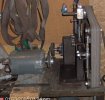
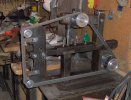
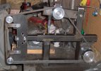
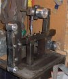
The main structural metal was box iron from the metal yard. The main tubes are 2 inch (OD) square and they are 3/16" walled. The inside box iron is 1.5(the inside box meaning the part that slides into the 2" to hold to from idler assembly). It is important to remember that there is a factory welded seam inside on the box irons, so I was careful not to make that a point of pressure on contact in the telescoping region. The part that connects the upper idler mount is rectangle box iron. The dimensions are 2.5" x 1.5" with 1/8" walls. I drilled an extra hole to play with where the pivot point should be. The rear bearings are from Orscleans Farm Store. The wheels ofcourse are of the finest quality from Mr. Frink. The 4x4 box iron base allows a stable mounting surface because with the bearings mounting on the 4x4, there is 7 inches between the furthest apart contact points. This lessens the possible vibration from having a weak bearing set up with the bears to close together, and the v belt system putting to much leverage (more like torque maybe) on them. I bought .750 shaft from the local machine shop, and then I cut the keys on a mill at work. The whole assembly is mounted on 1/4" plat. Cutting nice radices on the base plate is difficult with O/A. I used a 4 inch brass collect off the end of a weight bar and clamped in place. I had to adjust for the offset of the curf. About half the welding I did O/A because at that time we did not own a wire feed welder.
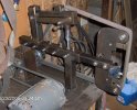
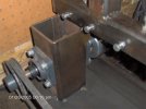
The front platen is 3/8" plate. I profiled everything with O/A and did clean up with files and an angle grinder. I made the grinding plate totally adjustable as I figured adjustability was the only way to ensure the entire belt be supported in the grinding area. The grinding plate(by this I mean the part you push against) can adjust out or in depending on application(I guess). I figured this would be a good feature for slack grinding. It is very important to have the holes for the 2 inch idlers in the front platen plate PERFECTLY SQUARE! When hand tapping for 1/2" bolts, it is nearly impossible to do so. I ended up using a mill at my summer job to clean up the 3/8 platen plate and to get the mounting holes square(because I didn't have access to the mill right away), I ended up welding one hole twice and the other once. It is better to do it right the first time, cause welded holes are very hard to drill and tap(even with a 1.5 ton machine)
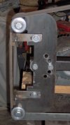
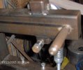
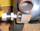
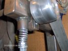
The Hexagonal tracking adjustment and hex counter screw I made on a lathe out of agriculture hex. stock. It I choose the hex. because it is easiest to adjust firmly with less effort. The arm depressing handle I made on the lathe too. I threaded it in to the other side of the arm, which you can see in one of the photos. In reality a bolt would have worked, but I wanted it to be removeable and knurled(plus it was fun).
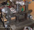
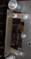
I may have put too many set screws in (5 in line with 90 degrees, 5 stagered at 180 degrees), but I wanted to ensure the tube was going no where. In reality 2 from each direction would have been adaquate. I have not yet used this grinder with new belts. I may need to shim the inner tube to work right with a better quality belt.
I now understand why Mr. Frink uses machined flats to make the arm acceptor and why he uses solid machined bar are the arm. Getting everything square with metal yard iron and mostly hand equipment(I did a majority of the work before having access to the mill and lathe...doh) is very hard to do. Having pieces cut square and straight is a essential for having the grinder work properly(i.e. limited belt wobble) Sometimes she works perfect and then other times there is a discernable wobble (1/32-1/64 maybe, just when running under no pressure)
Indian George, I will try to snap a few pics when I get home from college this weekend. I will be glad to try and explain everything I can about how I put this together if you have any questions(I am mainly qualified to speak about how NOT to do things
")
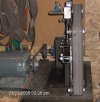
) The last photo in the line up thus far is one of it running(although I am not sure if that can tell you anything)
Things to do next....Get a big motor that I can't stop dead by pushing on the belt hard, make the grinding platform, put a cap on the 4x4 box, and maybe a little paint cause it is getting surface rust.
In hind sight.....What is I really wished to accomplish?? Well my goal was to make something as good as the KMG. Well, I frankly failed that goal. But in the process I learned things. Ultimately, if my goal was to just make knives, the wise thing to do would have been...(as a chorus now)....buy a KMG! I think in hind sight I would have bought the KMG. The KMG would have been cheaper(in terms of hours spent and materials) and would run better too. But all in all, I am happy I got the opportunity and result works pretty well.
Thanks for listening
-Luke
P.s. Please ask if I said something that needs more clarification.