Slipjoint spring/tang question

Sean Yaw

Gold Member
Joined
Feb 26, 2019
Messages
417
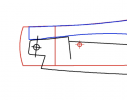
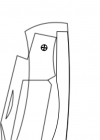
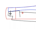
I am having a hell of a time trying to tweak a slipjoint design such that the spring tip is flush with the corners of the tang in both the half-stop and closed positions. These two screen shots attempt to illustrate what I am talking about: One where the spring tip lies flush with the corner of the tang and one where it does not (the spring tip overhangs the corner of the tang). Is there a standard way of designing the tang and pivot hole placement to achieve this? Generalizable approaches and education would be greatly appreciated. Thank you.
Screen Shot 2021-12-12 at 2.51.55 PM.png Screen Shot 2021-12-12 at 2.52.17 PM.png
 
Ah! There it is. Personally, I prefer keeping the spring as short as possible. It does need to be long enough to completely span the blade in the half stop. The blue/red drawing is where I would try to go.
 
Ah! There it is. Personally, I prefer keeping the spring as short as possible. It does need to be long enough to completely span the blade in the half stop. The blue/red drawing is where I would try to go.
I agree. That is what I am trying to get to for a pattern I am working, but I can't get the spring tip to be flush in both that half and closed positions at the same time. I feel like I am missing some geometric intuition for what should be done.
 
"Slip-joint Folder Designing and Building" by Steve Culver is the book that finally clicked for me. Clear drawings and descriptions. Not expensive. Buy from Jantz or Amazon. Nice guy too.
 
Base your knotch and tang on 1/3's,

Get the Steve Culver book as mention and he will show you how
 
If you have a pattern made, file the back square forward until the tang meets where you want it.
Plus one on Culver’s book.
 
The pattern with the more flush tang looks like the swayback jack from Chris Crawford's website you posted about in this thread. I looked at that pattern and it seems to me that the tang corner is actually slightly forward of the spring in the half-stop position. It also appears to be slightly behind the spring in the closed position, so this pattern also has a difference in where the corners of the tang are relative to the end of the spring in the closed and half-stop position.

I have never made a slipjoint, but I have drawn a couple and have been wondering about the same issue. I was really hoping somebody would reply with a solution, but it seems to me that maybe the problem does not have a perfect solution, depending on the constraints. It is easy if the rotation angles are 0, 90 and 180 degrees for the three positions, but if the rotation in the closed position is a lot less, say 163 degrees as in the pattern you posted, it becomes tricky. I am not sure if it is possible to avoid a gap unless the half stop is set to half of the closed angle, 81.5 degrees in this case. The first example below has the half-stop at 81.5 degrees and the corner is flush with the spring in the closed and half-stop positions. The second case has the half-stop at 85 degrees, and there is a small gap in the closed position. This gap becomes larger if I try to increase the half-stop angle to 90 degrees. Maybe I am missing something, but it seems to me that there is no way to avoid the gap other than setting the half-stop at half the angle in the closed position. I think the gap in the swayback pattern looks small because the tang is small, the error is split between the half-stop and closed position and the closed angle is much closer to 180 degrees (I think it is around 174 degrees). Like I said, I have never made a slipjoint (nor read the above mentioned book), so take all of this with a grain of salt.

5dIrMCj.png


8LlNGWX.png
 
Adam and wkfl already mentioned it but I'll 3rd it. Your backsquare determines what your after here. Grind off more and your spring gets longer on the tang. Take off less and it's shorter.
 
I'm known to ramble and the camera work couldn't be much worse, but at around 5 minutes in or so, I begin to explain how I map out my tang and blade geometry.


BTW, Draftsight is no longer free, though it looks like you already have a drawing program.
 
Drew: That's a very good video. I used to use Draftsight myself, then after the "no longer free" email I changed to NanoCAD. Works just fine and is totally free. Works with the same dwg files. Only problem I have with NanoCAD it's only a Windoz program with no Linux support.
 
Sean, I have thought about the layout problem a bit more and I think the only way to avoid the gap is to use a half-stop angle that is half of the angle when closed. I have tried to illustrate the reason for the gap below in the form of a step-by-step tang layout procedure.

Figure 1: Select a height for your spring, I chose 5mm for this example. To determine the diameter of the circle, pick a size for your tang. Twice the height of the spring seems to be common, so I chose 10mm. To get the diameter of the circle, multiply that by 1.41 (technically, divide by the cosine of half the half-stop angle α). I chose 15mm for the circle shown. Then draw a line from the origin of the circle to a point A on the circumference. A second point B and a third point C are drawn on the circle, each rotated by the half-stop angle α in the clock-wise direction from the previous point.

Figure 2: Align the circle so that point A is at the corner of the spring and point B touches the bottom of the spring. At this point, the first two corners of the tang are determined, points A and B. The third point has to be on the line BC, as that line will coincide with the bottom of the spring when the blade is rotated by the half-stop angle α. To determine the third corner of the tang and the line on which the kick will be, rotate the triangle AOB by the closed angle β in the clock-wise direction to create the triangle DOE. Connect points B and C and points D and E with lines (shown in red). The third point of the tang is on the intersection of lines BC and DE, and the kick is on the extension of line DE. You can now see where the gap you asked about comes from. In the closed position, point D is at the spring corner and the gap is the distance between point D and the corner of the tang found in the previous step.

Figures 3, 4, 5: Connect the points found in the previous steps to draw the tang, and test by rotating the tang around the origin by the half-stop and closed angles. You can see the small gap in Figure 5. To eliminate this gap, you have to make the half-stop angle half of the blade angle in the closed position, i.e., α = β/2. This will make points CD coincident, and the intersection of lines BC and DE will be on the circumference of the circle at C/D, resulting in no gap.

I hope this helps, let me know if anything is unclear.
MfOQduY.png
 
Try this.

Figure out the dimension you want the blade from the top of the spine to the bottom of the tang and draw it on some paper. It should be 2 parallel lines.
Minus 1/3" of the dimension and draw a line parallel from the spine.

So now you have 3 parallel lines.

Between the middle line and bottom line is 2/3 .

Divide that in 2 and place a dot.

Take a compass and put the point on the dot and the pencil on the middle line.

Now make a circle.

At the rear of the circle and at the front of the circle draw perpendicular lines.

That circle gives you the rear of the tang and the front of the notch.

Now you have the tang and spring notch.
Draw the knife in front of that.

Now I place the completed blade and the spring in my jig.

Move the spring so the tip fits where you want.

At half stop the tip of the spring should be even with the tang.


When full open it will fit into the notch.

You may have to tinker a bit to get the exact fit, but this will get you really close.

Watch this video and you will see the where the tip of the spring is in relation to the tang at half stop and how it goes into the notch.
 
Thank you, Hubert for the comprehensive analysis. A much less precise, intuitive, explanation could be: A tang that is a perfect square (and no kick), with the pivot in the center, will align with the tip of the spring at the same spot. However, as the size of the kick is increased (to raise the blade off the spring), the square tang's corner will creep back away from the tip of the spring in the closed position only.

This issue arose for me on a small knife with an unusually large kick. This large kick made the spring-tip/tang impact location very obviously different and is really the case where this issue is most obvious.

I agree with you that the way to make the spring-tip/tang impact location line up perfectly in closed and half stop is to make the half stop angle 1/2 of the open-close angle. I spent way too much time concluding that and coming up with a process for determining tang shape if you want that impact location to line up, at the cost of a non-90-degree half stop.

This issue is pretty moot, since the tang corners need to be rounded anyways for proper functioning, so minor changes in spring-tip/tang impact locations are not usually very obvious. Nonetheless, it was a good exercise to wrap my mind around what is going on and how to influence design. Thanks so much for all the time you put into this.
I'm glad it helped and since I plan to make some slipjoints sometime next year after I build a surface grinder, I needed to figure this out anyway. I actually thought of the solution last night in bed before I fell asleep. Maybe that's why the description of how to draw this is a bit cumbersome. I was thinking about this in terms of constraints in a cylindrical coordinate system, not about how to draw it most conveniently. It might be more intuitive to start drawing a line through the spring corner at half the half-stop angle with the vertical axis and then intersect that with a horizontal line half the tang height below the spring to find the pivot center. It sounds complicated, but it actually does not take any time at all to do this. I will go back and use this method for the templates I have drawn so far.
 
This is the process I itemized from my mental wandering:
1.Draw tang as square, put pivot at center, and put in kick.
2.Align pivot on spring in open and closed positions.
3.Set halfstop as ½ open-close angle.
4.Move spring back to halfstop position corner.
5.Set closed edge to that corner.
6.Set halfstop edge as spring edge.
Set your blade tip in closed position and lock in place.

At half stop the spring end even with tang and the rest will fall in place.

I draw a line on the spring at half stop and remove metal bit by bit to fit perfectly
 
Back
Top