Spyderco Tri-Angle Sharpmaker Angle adapters - Free

777 Edge

Dealer / Materials Provider
Joined
Sep 16, 2019
Messages
1,135
Hi guys,

For any of you following my thread on my Free 3D printable LeadingEdge sharpening system, "zyhano" and I were discussing designing adapters for the Sharpmaker.

I have 3D designed 19 different adapters to give your Sharpmaker a total of 14 extra angles to choose from, starting at 20 degrees inclusive (10 degrees per side), all the way to 60 degrees inclusive (30 DPS).

They slot into the Sharpmaker 30 degree "backbevel" slots.

Be sure to 3D print or CNC mill 2 of each one you want tot use (1 for each of your rods.)

If you don't have your own printer, then I suggest only having 1 adapter printed to start with and to see if it works with the shop's print settings, and if the print is accurate enough. Once you have tried 1 adapter and it works, then have the ones you want printed.

Here is where you can download my models in STL file format for 3D printing:
https://www.thingiverse.com/thing:4755125

Enjoy!

Note - Edit to original post - I added more angle options.
 
Last edited:
Hi, that's cool, could you provide a few pictures so folks have an idea what they'd look like and how they'd work with the stones in place?
 
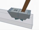
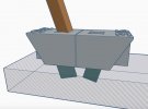
Sure, let me add a rendering from 3 sides of what it looks like and how it works.

The "invisible" part of the image would be the base of the Sharpmaker and the adapter would be in the 30 degree "back bevel" hole of the base.

In the renderings, I used the 28 degree (14 degrees per side) adapters and just 1 spyderco rod installed for reference of what the hole in the other adapter looks like.

EDIT - IMAGES REMOVED because I changed the design slightly. See the new images below in this thread.
 
Last edited:
Hi 777edge, that already looks great!

In a PM you said the brass protector rods cannot be used because the adapter overlays them.

I'm wondering if it is possible (strength wise) to angle the backside of the adapter (the side facing outward) so it creates room for the rods. There is 6mm room between the regular rod hole on the sharpmaker and the protection rod (edge to edge, smallest distance) and the rod is (eyeballing it) at about 50 degrees angle (where the 30 degree rod would be at 90-15 = 75 degrees angle relative to the base).

Maybe this would thin the adapter too much? Else the adapters could be offset in regards to the slot in the sharpmaker itself, moving them more inwards towards each other. I measure 15 mm edge to edge between the sharpmaker rod holes.

Also, the angles numbers could be on the side of the adapter instead of on the top.

The print shop I'm sending them to is about 5 euro per adapter with 15% infill and 0.2 mm printer (accuracy?) settings.

I can place the text anywhere but with 3D printing what you always need to consider, is how a FFF (Fused filament fabrication) printer actually prints the design. You should always think of orientation of printing and trying to use as little as possible supports in how it will be printed. Basically, think of it this way - it prints from the bottom up, layer by layer so if you have any level overhangs or level surfaces then they can only be printed with "supports" that you break off after the print is completed. With the text printed on the side, and with the print orientation of how I designed this, the text would then need supports below them and inside of them which will be a little messy and not practical.

How I designed this, allows it to be printed in the same orientation as how it would go into your sharpmaker. There will be the need for a support in the print for the bottom part of the rectangular adapter as it prints, but no other supports will be necessary when printing this. If you print it upside down, or on its side, then supports will be necessary for the bottom triangle and the insides of the slot. I hope it makes sense what I am trying to explain..o_O

Printing this with a 0.3mm layer height and perhaps about 60% or more infill should work for this. ("Infill" is how "hollow" the inside of a print is, basically to save print time and plastic) Normally I print most of my functional designs like this one with 100% infill, which makes it a solid and strong block with some added weight.

As for the brass rods, I am sure I can come up with an idea around them but not having a sharpmaker myself makes this very hard to do. Anyone feel like sending me one? I am sure I can probably come up with some killer upgrades for it if I had one myself.;)
 
I just finished making some changes to allow the use of the brass hand protection rods. I added two 60 degree cutouts on each side, and left a stability support between where the brass rods go.

I also added more angles, so now with these adapters you will be able to sharpen from 20 - 60 degrees inclusive (10-30 Degrees per side) with your Spyderco Tri-Angle sharpmaker.

As a bonus, I think they will also work well with single bevel / chisel ground edges. If you use the 20 (10 degree) block on one side, and on the other side of the bevel you can use whichever angle corresponds to your single bevel grind, it should make sharpening chisel ground knives easy too.

Please print / CNC a set for yourself and let me know what you guys think.

I would suggest that, if you don't have your own 3D printer, only have 1 printed first from a shop or printing service to see how accurately they are printed and if they work. Don't print the entire batch because the shop's printer settings may not be as accurate as required. I designed them to be an exact fit.

1 - TOP.jpg

View attachment 1506776

3 - SIDE.jpg
 
Last edited:
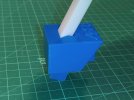
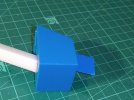
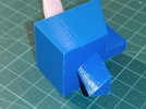
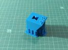
Here is an actual print I did to test it today. I don't have a sharpmaker, so I printed a "dummy" rod with 13mm sides.

The LAST photo is just for interest, what the print looks like before you remove the supports necessary for printing.

IMG_20210210_203550.jpg


IMG_20210210_203634.jpg


IMG_20210210_203704.jpg

This is how it looks, coming straight off the printer. The supports are just broken off easily:
IMG_20210210_201614.jpg
 
That looks pretty slick 777Edge!
I've just left you a PM with some more observations regarding the base of the adapter. Can you do a check to see if the base of the adapter fits in another adapter? (because of the measurements doublecheck I did on your raw design input)
 
Back
Top