And another DIY forge press thread (parts from tractor)

Joined
Feb 10, 2023
Messages
52
Hello!
To avoid necroposting or derail someone's thread, I decided to post my own. As title says, I have stupid idea to make forge press from parts, sourced from tractor. To be precise, it is old forest skidder or something like that. Machine itself is 6,5 tons, with capability to carry another 2,5 tons. That would be the donor for my project. And no, I don't plan to restore it.
There are two cylinders, piston is 110mm (4,3in), rod is 40mm (1,57in), cylinder length is 34cm (13in). Cylinders move up or down carry bed, where 2,5 tons of stuff (usually logs) is transported.
Oil pump is rated for nominal 2300psi with max 3000psi. I have found conflicting info for flow rate, as low as 75l/min (19gpm) and up to 27-30gpm. It is single stage. Machine is really old and I don't have documentation for parts specs. I know nominal engine rpm, but without taking pieces apart, I don't know oil pump rpm. It is driven by gears, I can calculate once I have it on table. Engine is seized, machine itself is scrapped.
Oil tank have built in filter, capacity is at least 20l (5gal), haven't really measured it. Control unit or directional control valve (if translated correctly) have P40/75 name, for what it is worth, I don't know. Again, conflicting info in different manuals, I found one what states flow rate 75l/min (19gpm).
I have plenty steel and welding skills to make forge press beast, at least in my head there is idea. If it is viable, it would be project for winter. I haven't calculated potential press force or ram speed, for now it is just an idea. I would like to use both cylinders, they are in parallel in skidder, with metal couplings between them. I just need to bend oil tubes a little, because now cylinders are ~60cm (23in) apart. In press they should be side by side, right? Assuming I have most parts to make forging press, I have thought about powering such unit - no way my home electric grid can handle that. I have option to use diesel generator (8kvA), or petrol engine (12hp). If I go diesel generator route, I already have 2 identical 4kw 3phase motors. I can buy 7,5kw (10?hp) motor. All 3 phase, AC 220/380.
Well, there it is. Feel free to throw any idea or question at me. I would love to brainstorm about all that, to learn and avoid mistakes. Maybe my idea is wrong, maybe I don't have all parts what I need, maybe what I have is not optimal for what I want to build, that is for discussion, so shoot away!
 
The cylinders are matched? The 4.3" bore at 2300 psi would give you right at 16.5 ton. A 16 ton press will work great, but if you're wanting a 33 ton press parallel them should get you that. I would think you'd need to calculate the surface area of the piston in the 4.3" ram, then double that, then calculate the diameter that results. It won't be 8.6" :) Most likely in the range of 6" diameter or so. I think that's how it would work - I'm NOT a hydraulic expert by any means.

Another concern would be the ram speed with both paralleled. You can check speeds here with different setups. https://www.baumhydraulics.com/images/calculators/cyl_speed.htm

This calculator will get you the tons for the press: https://www.baumhydraulics.com/images/calculators/cyl_calc.htm

A possibility would be the 19 GPM is at the engine rpm, while the 27-30 GPM would be at max rpm the pump is rated for? The 4kw motors should handle the 16 ton press just fine, with some to spare. The RPM of the motors will determine output of the pump. Is your diesel generator a 3ph unit?
The 12hp petrol engine should work just fine for the press- if you build for 30 ton and the 12 hp has a hard time you can always drop the pressure to maybe 1800 psi for a 25 ton rating. Again, I repeat I'm NOT a hydraulic expert by any means.

For 16 ton the 5 gallon tank should work just fine. If paralleling the two 4.3" cylinders I expect you'll use the existing method of hydraulic connections. Not sure how much the cylinders need balancing on the skidder you've got. I'm not sure how to make sure the two cylinders are sharing the load equally in a press, but this does need to be determined.

Good luck with your build and keep this thread updated as you make progress.
 
Yes, cylinders are identical. They are at work in parallel, there are metal tubes connecting them. That's why I want to use them both, I have all the peripherals and, go big or go home... They work in parallel just fine in the skidder, so I assume in press it will be the same.
Ram speed is another concern. That is part of what I can compromise. If generic skidder pump is too slow for forging, I can seek for more powerful one. All I want is to use what I have on hand, if possible. I can weld extension for oil tank, if 5gal is too small, I can use 30-40hp petrol engines, if 12hp is too small. Diesel generator is 3phase, it has two outlets, so I was assuming I can run two 4kw motors parallel. If that is the route I take. I have option to use 40hp petrol engine, if 12hp is too small. It may be overkill, but I have it. I am not restricted with space or noise, only restriction is to build it off grid. Power it from generator or engine (12hp or 40hp).
 
I would suggest a larger oil tank for running the cylinders in parallel. 40L would be better. You could start with what you have and see how hot the oil gets.
 
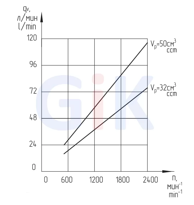
Little update and questions. I took apart oil pump and measured dimensions - shafts are 1inch, gear teeth is 32mm wide (1,26in) and gear diameter is 55mm (2,16in). Now I can compare to newer versions for who I can find technical specs. Or can I calculate flow rate from my measured dimensions? I am still learning all that stuff. Rpm would be variable in calculations, but what is displacement volume? How can I know that if I don't have manufacturers data? Skidder datasheets says pump is НШ-60В, where 60 is cubic cm working volume. That can't be displacement volume, right?
Closest what I found from what is still being made is that in picture:
MTZ-nsh.png

They don't make НШ-60 anymore (if that is what I have), models now are НШ-50 and НШ-71. If I use manufacturers data and my extrapolation for 60, then I get 35gpm at 2400rpm on pump shaft. Does that sound realistic?
 
I wouldn't have a clue to comment on the volume of the pump from the gear measurements. One thing to think about, the pump works(ed) just fine with those two cylinders on the skidder and volume was sufficient to work the cylinders. Not sure what rpm the skidder motor was actually turning the pump, perhaps you can fingure that out from the skidder? I'd think about using the pump on hand with the press. If it works - great. If it's a tad slow at that time a replacement pump could be looked for.

Agree with Stacy - for both rams a larger oil tank might be needed..... but the existing tank worked for the two cylinders on the skidder. The percentage of time the cylinders were operated on the skidder vs time the press will be working the cylinders would be a consideration. I suspect the original 20L tank would work pretty good, unless you're planning constant work 8 hrs/day with the press.
 
Well, pump shaft is one inch and it weights little over 6kg, if we compare to yaegoo 11gpm, then yaegoo has 1/2 shaft and weights 2,82kg. With that in mind, my calculations (35gpm @2400rpm) doesn't sound too unrealistic. Where do I get 2400rpm? That's picture from manufacturer. These numbers are for НШ-32 and НШ-50. I believe I have НШ-60, version 50 is lighter about a kilo, so I am optimistic.
functional32_50A.jpg.webp

I agree about oil tank. I will build first as is, and then add bigger tank and/or chiller coil, if needed.
 
It sounds like a big pump. From your numbers, probably 27-32GPM.
I would use all the parts you have and make the press. If you need a bigger oil tank or a different pump, you will find out. They can be changed easily.
 
First - thanks for responses, it really helped to make order in my head. Now it is real project, not "what if" dream.
Second - I have shoulder injury and won't be able to work 100% for month or so. As I said in beginning, it is project for winter. Meanwhile I need to learn what else is needed (pressure gouge, new hoses etc.). Open question is how to power this beast. To be precise, how much power is needed. I played with calculators, if I get 25gpm, that would be 12,5gpm for one cylinder, and 3,3inch/sec. Now dumb question - speed can be too much? Is there optimal range for that? Speed is function from gpm and gpm is function from pump rpm, so I need to design around that. If I use electric motor, then rpm is constant, if I use petrol engine, then rpm is variable +-200 or so around engine normal working rpm.
 
How much HP? I don't know, but for a 25 ton press Coal Iron presses use a 3200 rpm 5 hp motor with a 13 gpm pump. So, I'd think your 4KW (5hp) motors could be used since you've got 3 ph power available. That would depend on the GPM rating of your pump. "IF" it's too much, it could be changed out for a smaller pump in the 15 to 20 GPM range.
 
If I understand correctly, my 4kw motors are very similar to those used in Coal Iron presses. We just run 50Hz, so our rpm is lower, approx. 2880rpm. I need to think how to make twin system. Pulleys and belts? Then I can change pulley size on pump shaft if I need different pump rpm.
 
I’ll add a few formula/rule of thumb ideas for hydraulic systems. Your donor reservoir might be on the small size. Mobile systems typically run a reservoir 1.5-2x the system volume and incorporate external cooling. An industrial system reservoir is typically 4-5X the system volume to allow for heat and air dissipation, external cooling is also used.
Pump flow=cc/rev x rpm/1000 to get l/min, l/min to gallons multiply by 0.2642.
HP=PxQ/1714 if using psi and gpm, kW=QxP/600 if using bar and l/min.
There are 0.746kW in 1 HP
F=PxA (force=pressurexarea). If force is desirable in lbs, use psi and square inches.
There are 231cubic inches in 1 gallon.
Cylinder speed is a function of flow, you will need to know bore area and stroke length (or to make the calculation easier, imagine a 1” stroke length). You can then calculate the cylinder volume over 1” and convert to gallons.
At 28GPM, a D05 valve might be too small, and can create a fair amount of heat.
Cylinder area ratios are important when calculating valve size: a 2:1 area ratio cylinder retracting with a rod input of 28GPM will have to evacuate 56GPM from the cap end. I hope my gibberish isn’t too hard to follow. Best of luck on your project.
 
I had a large log splitter with similar size pump and it ran off an 11HP honda engine. Gas is usually twice what electric is, so 5-6HP electric or 10-11 gas.
You can put the gas motor, hydraulic fluid tank, and pump in a shed on the other side of the shop wall and run the hydraulic hoses through the wall to the press. This makes the press simpler to build and keeps all the noisy stuff outside.
 
Forgive me if I sound dumb, but there are few things I still don't understand. Cylinder area ratio - that is something to do with rod volume? In that 2:1 example then you have twice the ram speed on retracting vs expanding, because on expanding you have all the area behind piston, but on retracting half of that volume is already taken by rod. I think I got this one.
Next - what is limiting factor for oil pump pressure? Mine is rated for nominal 2300psi with max 3000psi. Is pressure function from rpm, the same as flow rate? Or is it regulated with overflow valve? And regardless of rpm, you will get those psi, sooner or later, depending on gpm?
Funny thing is, I have restored power steering columns for my tractors in farm, worked with various hydraulic machines, but now I know how much I don't know. Designing and understanding something takes much deeper than just mere repairs by the book...
 
I think you've got the cylinder area ratio correctly - The expanding (extending) speed is based on the cylinder area, the retract speed is based on the cylinder area minus the rod area. This is shown clearly in the link posted above for speed.

Perhaps Stacy or Onies will comment to be sure I'm correct when I say you're right on the limiting pressure. I think the max pressure is determined by the pressure relief valve that is used to adjust max pressure, usually contained in the control valve. Slow rpm builds pressure slowly, higher rpm builds pressure faster. The flow rate is determined by rpm. Low rpm has lower flow rate, higher rpm has higher flow rate. It seems with the gear pumps flow rate is directly linked to rpm, 1800 rpm has half the flow rate as 3600 rpm.

I never worked with hydraulics until I got this press. It was so many years ago when I grew up on farm and worked with farm equip we didn't have hydraulics, it was all manual. Dad's farm equip got hydraulics well after I left home.
 
Run the pump at the rated RPM. Don't slow it down.
Set the check/bypass valve to the desired pressure - usually around 2500PSI.
Your press should have a very good speed with the specs you have given. Faster is better.
 
A gear pump is a fixed displacement unit, meaning the flow is determined by shaft speed. Typical industrial units will run at 1775 rpm, but can run slower, or slightly faster. Exceeding the rated shaft speed can cause problems, from catastrophic failure to high levels of aeration as exceeding the rated shaft sperd can draw air through the shaft seal. As a fixed displacement unit, your primary pressure control is your relief valve, and it should be set at full pump flow.
 
Project update.
Over the weekend I went over all my steel cemetery - it is a special place where broken or similar kind of stuff goes. I got that from my father who started it with his, oldest stuff there is 1950-60. I dug out truck frame, measured some other steel, took some photos.
Well, now the numbers. Skidder frame is 3,7meters long, made from C-channel, which is 40cm(15,7in) tall, with 11,5cm(4,5in) flanges. With two sides, I have pretty much steel. Cross section - flanges start at 9mm, goes to 15mm at corner, then thins out to almost 6mm at middle of width at 20cm mark. Frame is constructed from two pieces, 85cm apart, and there is already housing for cylinders, where one end of them is secured with frame. I feel it would be too wide to use all that as is, so I wanted another options. This is where truck frame enters the scene - so, I have C-channel, 2inch flanges, 4,7inch back. thickness starts at 5mm, well, I know there are standards, but I have only outside measurements. This I have 2 pieces 2,5meters long. Then above that I have second frame, made from 5mm thick steel, at one end it is like C channel with 6,7inch back/2,4inch flange, at other end it is 9inch back/2,4inch flange. All 5mm or 1/5inch.
This frame is narrower than skidder frame and I feel like if I take both frames and incorporate them in one, back to back, I would have enough beef for press.
 
Back
Top