Well, my calculations are 35-40ton, depending on psi. H frame, obviously, it is much simpler construction to make. In the picture it is not visible, under that frame is another one, C-channel, 2inch flanges, 4,7inch back. I can scrap all this and sell that to real scrapyard, then buy something, or I can use what I have. That is the question. Make frame from parts in picture, make frame from skidder frame, or buy metal for build? I'm too dumb for calculator, sorry, Ken. I read that knifedogs thread with Ford52 calculations, but my computer skills are not on par to do something similar. Anyway, nothing changes today or tomorrow, I'm still accumulating scrap and learning.
-
The BladeForums.com 2024 Traditional Knife is available! Price is $250 ea (shipped within CONUS).
Order here: https://www.bladeforums.com/help/2024-traditional/
You are using an out of date browser. It may not display this or other websites correctly.
You should upgrade or use an alternative browser.
You should upgrade or use an alternative browser.
And another DIY forge press thread (parts from tractor)
- Thread starter lynx85
- Start date
Money permitting I'd sell all the scrap I could round up and buy good steel. Might be able to find that at scrapyard and just trade.
On how to size the steel for 40 tons, there are a bit of calculations that are not that hard to do. BUT - like a navel architect course I was studying said, now you've done all the calculations, go down to the marina and look at the boats there and see if your calculations make sense. Look around at some of the 40 ton presses on the market and see how large they are. With the "H" style frame angle iron works good. I-beam will require lots of care in attaching the bars across and at bottom to be sure the stress is spread over the total I-beam area.
This YT video has what looks like a good idea for attaching to I-beam to spread stress over total I-beam:
Here is another really good press build:
Well, there are one problem with all youtube video's - everyone can have some. By no means I try to downgrade someone's work, not at all, but info can be conflicting. Many times it is obvious - used material is overkill. Sometimes I look and wonder, how that thing is still not exploded. For example, I have few welding courses education - I was told that short arc mig is a no-go on structural. You need enough amps (powerful enough machine) for spray transfer. If your mig can't do spray, then stick (MMA) it. I see plenty video where this is the case. Anyway, back to my scrap: today I took cylinders from skidder. I plan to use that frame, just cut out middle part to make it narrower.
I'm "assuming" the round rod the cylinders are attached to at top are solid? Even with that you might find it not strong enough for a press. Consider the cylinders use in the skidder - It will never have the full 40 ton (or whatever the max stress is) since it's just pushing down to lift front of skidder, OR, lifting the load which will never be anywhere neat 40 ton. In a press it there will routinely be 40 ton of stress on the round rod. Not saying it won't work, just something to think about.
On the welding - I would NEVER consider using my mig welder for structural - it's not "hot" enough to get much penetration. For structural fabrication I'd use my stick welder.
On the welding - I would NEVER consider using my mig welder for structural - it's not "hot" enough to get much penetration. For structural fabrication I'd use my stick welder.
Cylinders are attached to 3" round tube with wall thickness 0,6". (75mm and 16mm). I imagine that forces there work mostly to shear material, not to compress or deform. I need that little opening because cylinders mounting screws are tightened there. Above all that - well, I can weld everything there.
For press frame I have changed my initial thoughts to use that truck frame (posted picture earlier). I have O-beam with overall wall measured at 6,8 square inches. My calculations, if correct, show approx. 130ton pressure before elastic deformation. Is it overkill? Maybe. But I, like everyone else, work with what I have. And to continue there - my single stage pump is different animal - looks like it requires 41kw motor. Skidder had 5,4liters diesel engine, well, you learn something new every day...
Added day later: 130ton estimation is if I use O-beam as a side stand AND add truck frame as a slide guide. Then I have total of 9,3 square inch. That way I have to buy electrodes, cutting wheels, but not steel.
Last edited:
Ok, I have update for parts, design and few questions.
First, I think I have all the steel necessary for press build. I got 18x18cm (7x7in) H-beam. Not enough to build all from that, but that is better than my starting plans. Also I took skidder axles, where track support wheels go, and my plan is to hybrid them with h-beam. I made sketch with cross section of that. There are added elements on both sides, and total cross section is 9 square inch, not counting welding beads. Round tube is skidder axle, flat portion is half from h-beam. All is welded to closed contour.
And now my question - look at my cylinders in the picture few posts back - top connecting with that 3in tube. In picture cylinder can move like swings - perpendicular to press face. There are little play from side to side, but it is so small that I count cylinders locked in that dimension. Should I rotate cylinder mounting position by 90 degree or is it ok to use as is? Moving part in press I plan to make from that 18x18cm h-beam offcut, with some reinforcements to add sliding surface, total it can be 30cm(12in) by 18cm. I don't plan to work on one end of dies, so tilting should not be a problem. However, if there is possibility to break cylinder mounting bracket during work, I would like to avoid that and make changes in design, if necessary.
I don't see a problem with your mounting ideas. Yes, there is a small amount of play, but I'll bet with the top of cylinders mounted to the round holes the lower end would have enough slack to move at least 12mm, or perhaps even 25mm to the side. That should be more than is required.
Keep posting to keep us updated
Keep posting to keep us updated
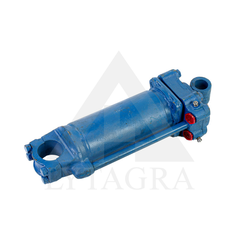
Top end clamps on tube virtually without runout, cylinder is designed to swing front to back, without moving left or right. In my local tractor supply shop I can buy 5inch cylinders (200eur/each) if I ever wanted to upgrade, but I doubt it, 4,3in is not that small. Anyway, there is picture from that shop, to better understand clamping end.