HT Oven Build Question

Joined
Feb 14, 2014
Messages
20
Greetings All! I have been trolling around the site for several years and found many many answers to everything I have worked on and had an issue with but I’m running into quite the brick wall on something this time. I am building a smallish HT oven and am at the point where I am building the control box but can’t find a simple wiring diagram for my application. I am trying to keep it uncomplicated. Here are the specs:

Yeah, I know... “not another oven dummy...”

SYL-2352P PID
40A SSR
Heat Sink
K Type Thermocouple
16 ga Kanthal A1

I will be winding my own element coil and have a good grip on all that as far as coil spacing and the math. Shooting for around 1300-1500 watts. The chamber is 4” wide, 4.5” tall, and 11” deep. I will be running the oven on 120vac because I don’t have 240vac set up in my work area yet. It’s coming but will be a while yet. I am not putting a door switch on it and no indicator lights. My plan is for the PID controller lights when powered up will indicate the oven is on, a power switch, and that’s it. When I want to go in the oven and open the door, I’ll shut the controller off with the mains switch. Trying to keep it simple. I’ll build a 240vac larger oven with other bells and whistles sometime in the near future and have found plenty of schematics for that type of a build but nothing for what I’m trying to build.

I have a grip on the basics of wiring the PID and associated stuff needed but want to find a good proven schematic to validate what I think needs to be done to wire it up safely and effectively. It should also be noted that I understand electrical wiring for both AC and DC circuits. Not a complete newbie here.

Hopefully someone will have a schematic or link that will help. I’ve looked high and low and scoured this site as well as others and have had no luck.

Thanks in advance for any help.

V/R
Steve.
 
IIRC, the schematic is in the PID sticky.

The basics are:
A 120VAC line goes to the PID. Fuse this line for 1 amp. There is also a ground to the PID.
The DC low voltage line from the PID goes to the SSR ( usually terminals 3&4). Observe polarity.
On a 120VAC unit, the hot power feed goes to terminal 1 on the SSR. Terminal #2 is where one end of the Kanthal coil is connected. The neutral power wire goes to the end of the Kanthal coil. Fuse the power line at 5 amps above calculated current draw.
If the unit will run on 240VAC, use two SSRs, with the coils comnnected to terminal #2 on each and the twompower wires connected to the #1 terminals. The DC line can be jumpered from one PID to the other. Put a fuse in each hot leg.
 
Last edited:
IIRC, the schematic is in the PID sticky.

The basics are:
A 120VAC line goes to the PID. Fuse this line for 1 amp. There is also a ground to the PID.
The DC low voltage line from the PID goes to the SSR ( usually terminals 3&4). Observe polarity.
On a 120VAC unit, the hot power feed goes to terminal 1 on the SSR. Terminal #2 is where one end of the Kanthal coil is connected. The neutral power wire goes to the end of the Kanthal coil. Fuse the power line at 5 amps above calculated current draw.
If the unit will run on 240VAC, use two PIDs, with the coils comnnected to terminal #2 on each and the twompower wires connected to the #1 terminals. The DC line can be jumpered from one PID to the other. Put a fuse in each hot leg.

sorry to butt in here, was roaming around the webs looking for advice on my ht oven build, which is 240v from my design. I see you suggested two PIDs for 240v? may I ask why? or 2 solid state relays?
 
With the 220/240 volt current in the USA you use two hot lines. If you use one SSR it will turn them on and off just fine. However, the coils are always hot to ground because the other leg is not switched. Were you to reach in to put in or take out a blade while holding the door open and you touch the coils (even with the power off or with a door interlock) you could get severely shocked. That is why you use a DPST power switch to shut off both legs when turning the oven off, and two SSRs to assure the coils are not live unless you intend them to be during firing.

UK, EU,and Asian 220 volt waveform and wiring are very different from the USA/Canada. When looking at HT oven builds, make sure you see where the creator of the post lives. We have had that cause confusion here in Shop Talk many times.
Another good reason for everyone to fill out your profile and show where you live.
 
IIRC, the schematic is in the PID sticky.

The basics are:
A 120VAC line goes to the PID. Fuse this line for 1 amp. There is also a ground to the PID.
The DC low voltage line from the PID goes to the SSR ( usually terminals 3&4). Observe polarity.
On a 120VAC unit, the hot power feed goes to terminal 1 on the SSR. Terminal #2 is where one end of the Kanthal coil is connected. The neutral power wire goes to the end of the Kanthal coil. Fuse the power line at 5 amps above calculated current draw.
If the unit will run on 240VAC, use two PIDs, with the coils comnnected to terminal #2 on each and the twompower wires connected to the #1 terminals. The DC line can be jumpered from one PID to the other. Put a fuse in each hot leg.
Thanks. I’ll continue searching for a schematic. Visited your website and am about to order some blanks. Great stuff!! Cheers!
 
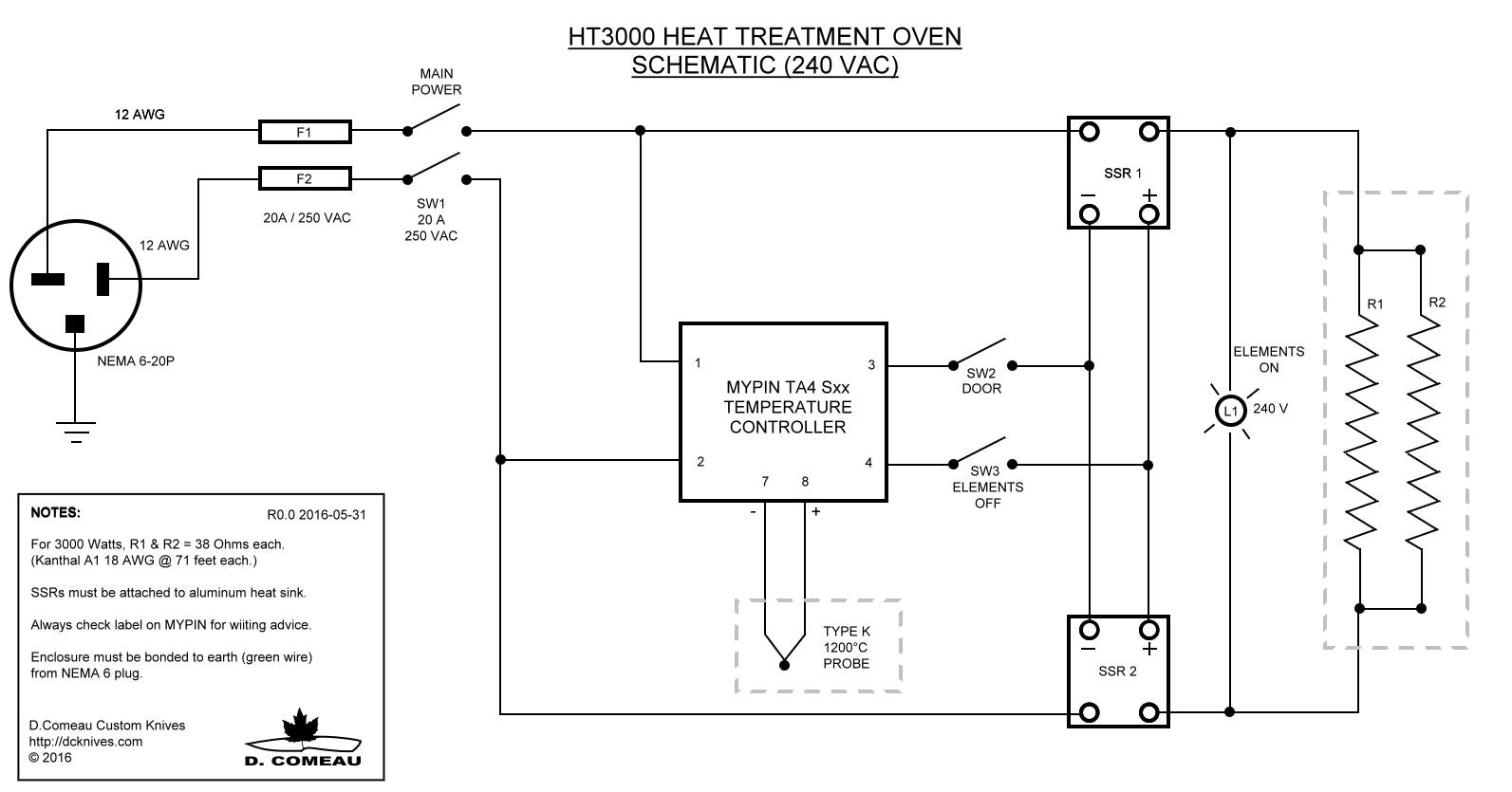
Here is what you want:
https://www.bladeforums.com/threads/heat-treat-oven-wiring-schematic.985651/
The schematic is in the PDF in the first post.
Thanks Stacy. I have that diagram already saved for a future build. Its a 240vac oven with all the bells and whistles that I will build when I have 240 available in my work area. I'm building a 120vac unit simplified right now. Like I've said before, I think I've got a good working knowledge of how to set it up but have not been able to find any wiring schematics for the build I'm doing. Hopefully I'll find something to confirm what I have written down so far. Your info above in post #2 helps and I appreciate it.

V/R,
Steve.
 
With the 220/240 volt current in the USA you use two hot lines. If you use one SSR it will turn them on and off just fine. However, the coils are always hot to ground because the other leg is not switched. Were you to reach in to put in or take out a blade while holding the door open and you touch the coils (even with the power off or with a door interlock) you could get severely shocked. That is why you use a DPST power switch to shut off both legs when turning the oven off, and two SSRs to assure the coils are not live unless you intend them to be during firing.

UK, EU,and Asian 220 volt waveform and wiring are very different from the USA/Canada. When looking at HT oven builds, make sure you see where the creator of the post lives. We have had that cause confusion here in Shop Talk many times.
Another good reason for everyone to fill out your profile and show where you live.


ahhh ok I think that clears it up... just 1 PID correct? (I see up top that you said "If the unit will run on 240VAC, use two PIDs, ")
anyways... that actually helps tons, I read through all the stickies which included the post you attached. I will follow that schematic with my 240vac/12.5amp/3000w build. I will adjust fuse amps accordingly. thanks Stacey!
 
Here is what you want:
https://www.bladeforums.com/threads/heat-treat-oven-wiring-schematic.985651/
The schematic is in the PDF in the first post.
IIRC, the schematic is in the PID sticky.

The basics are:
A 120VAC line goes to the PID. Fuse this line for 1 amp. There is also a ground to the PID.
The DC low voltage line from the PID goes to the SSR ( usually terminals 3&4). Observe polarity.
On a 120VAC unit, the hot power feed goes to terminal 1 on the SSR. Terminal #2 is where one end of the Kanthal coil is connected. The neutral power wire goes to the end of the Kanthal coil. Fuse the power line at 5 amps above calculated current draw.
If the unit will run on 240VAC, use two SSRs, with the coils comnnected to terminal #2 on each and the twompower wires connected to the #1 terminals. The DC line can be jumpered from one PID to the other. Put a fuse in each hot leg.
does this look like it will work properly? Thanks again for the assistance.
https://imgur.com/a/lQNp9M2
 
HT-3000%2BHeat%2BTreatment%2BOven%2BSchematic.png
 
https://imgur.com/a/lQNp9M2
This will work, But I wouldn't do it that way.
I always suggest switching both conductors of an exposed coil heating element.
36 years of working electrician/millwright, my experience is about 8-9% of 120V receptacles I encounter are wired backwards.
In trying to keep this small oven simple, how would you suggest switching both legs of the potential current to the element? I understand your point completely.

V/R,
Steve
 
In trying to keep this small oven simple, how would you suggest switching both legs of the potential current to the element? Steve
Just like shown in schematic above, a relay (SSR) in each leg of circuit to heating elements.
 
While I understand Lieblad's concern for improperly wired sockets, that can be simply checked out with a $5 receptacle tester.

The need to switch the neutral on a 120 VAC circuit is not really needed.

BTW, the door switch is usually a roller switch or other momentary contact device. Open the door and open the LV circuit.
 
Back
Top