J & L Drive Wheel Removal

Joined
Aug 6, 2009
Messages
13
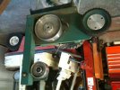
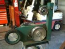
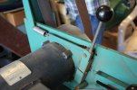
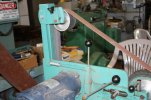
I have one of the later J & L Grinders whose drive wheel I need to move outward for proper alignment and/ or remove for service,

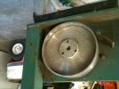
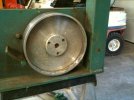
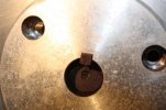
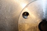
There is a set screw, that I have removed, in the hub that is accessed between the drive wheel and the vertical motor mounting plate. There are also three cap screws in the outer face of the hub that have been removed.

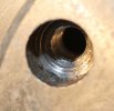
I ran some Kroil penetrating oil into the empty set screw hole and got it to run out of the keyway shaft end, but can not get anything to budge.

Can someone help me with how this drive wheel is constructed, and how it has to be removed.

Thanks,

Stan
 
I've no specific experience with that one, but
"three cap screws in the outer face of the hub that have been removed."

makes me think that there may be a tapered clamping force applied with those screws.


My next move would be to lightly tap the wheel with the smallest hammer you have.

100 tiny taps.


photos would help if you can
 
If you removed 3 bolts, is there 3 threaded holes to screw them into? Not the holes from where you removed them, but 3 others. If so thread them in and tighten them to release the shiv from the hub. pics help. Jess
 
Two photos are attached. There is no second set of drilled and tapped holes in the center hub to utilize to pull the center section out. The screws do go thru the outer piece and appear to be drilled and tapped in the drive wheel.

It would seem, as suggested, that the construction is such that the hub slides over the shaft with the drive wheel loosely on it, and then the three small cap screws pull the hub and drive wheel together to energize a clamping force.

What is still somewhat puzzleing to me is why there is also a set screw on the back side of the hub, which I have removed, if it clamps up like we think.

I gave it a rest last night after the "100 taps" with a plastic face hammer and some prying. I did not want to get western with it since all these parts are aluminum. Best to go to bed and think on it some more in the morning.

Thanks for your continuing help.

Stan
 

Attachments

  • photo(2).jpg
    photo(2).jpg
    47.4 KB · Views: 36
  • photo.jpg
    photo.jpg
    40.3 KB · Views: 38
If you prefer looking at photos right side up, try these.

Stan
 

Attachments

  • photo.jpg
    photo.jpg
    40.3 KB · Views: 28
  • photo(2).jpg
    photo(2).jpg
    47.3 KB · Views: 31
put the cap screws back in the , leave them loose and tap them with the hammer . You will be driving the drive wheel back , off of the tapered hub .
 
Good suggestion Jack! I wonder why I did not think of that.

However I have now tried that without success, but did not get too heavy with the hammer so that I would not damage the threads in the driver pulley.

I think I will turn a piece of round stock or tubing that will swallow the hub, so that I can tap a little harder on the wheel.

Also thinking about heating the wheel with a heat gun to expand the wheel away from the hub and tap on my driver.

Thanks,

Stan
 
are you sure it is the drive wheel that is tapped ? could it be that the tapered hub is in the back behind the drive wheel . This would explain the set screw , the back hub is threaded . With the set screw locked , you put on the drive wheel and the bolts then push the drive wheel on to the rear hub . If this is the case , then you need a wheel puller .

Just a thought .
 
Yes, I am confident that the Wheel is drilled and tapped.

Looking into one of the three C-Bores in the Hub I can see the threads in the wheel, approx 1/4 inch of threads.

The drilled and tapped holes goes completely thru the web of the Wheel. The hub is .437 thick (nominal) from its face to the wheel web. It is C-bored .332 deep for the cap screws, leaving about .100 thickness for the screws to grip. The screws are 1/4-20UNC x .375 LG +/-1/16 (hand ground to length). This leaves 1/4 inch or one diameter of thread engagement in the wheel web. (Not much for aluminum.)

This Wheel is 2 1/8 wide x 8 1/2 diameter. The original design (or at least an earlier design) 8 1/2 J&L drive wheel was one piece, and simply set screwed to the motor shaft. I'm not quite sure if this wheel is designed with a taper to energize the clamping to the motor shaft, or if it is made so that it can be used with a different hub, say for a larger motor shaft which one might encounter on a higher horsepower motor.

This motor is a 1 1/2 HP Perm Mag DC variable speed type. The grinder was purchased with a fixed speed motor and converted to the variable speed arrangement by the original owner. All factory parts I feel confident.

I will go have another try at it now that it has cooled down a bit here. I haven turned my "driver" yet.

Stan
 
I had hoped that someone with my exact Drive Wheel might have had theirs apart.

I'm not sure how many J&L's there are out there, but as an engineer I am impressed with John Leblanc's considerable design skills, Quite a clever designer! I just recently ran across his horizontal belt grinder on the web and see he used a very similar if not identical belt tensioning system on it. I want to "me too" that one or at least borrow from it. I doubt the wife will tolerate another big price tag grinder purchase. Does anyone know how many of the horizontals John sold?

Stan
 
I've only seen a very few photos of JL's and none of the tension system.

Can you post some good pics of that sometime ?
 
I think you are correct Stan . That may be a universal style drive wheel with different hubs for different shaft sizes . Whether it is tapered or not is unknown . I was searching and found both styles . This is driving me nuts because I have worked with many different styles in the trades .
 
If you trust the three holes in the hub/wheel, you could take a piece of 1/4" or 3/8" plate, drill it to match the holes with clearance holes for the cap screws, and drill and tap a hole in the center for a 3/8" bolt. Installing the drilled plate with the cap screws , then turning the center bolt in onto the end of the drive shaft would exert pulling force on the wheel/hub.

Don't do it if you think the threads would merely shear out of the aluminum.
 
I've only seen a very few photos of JL's and none of the tension system.

Can you post some good pics of that sometime ?

I don't know how " good" these photos are, but here are a couple of shots of the Belt Tensioning System on the J&L that I have.

There are several good features, among which are indirect spring loading of the belt (see photo), and the amount of tension is adjustable simply by going one notch more or less on the spring loaded tensioning lever.

These features make it easy to get the tension right for good tracking and not over tensioning which ruins belts. It is easy to slack the belt overnight so the joint is not stressed during what may be high humidity evening hours.
 

Attachments

  • IMG_5379a.jpg
    IMG_5379a.jpg
    42.3 KB · Views: 12
  • IMG_5383a.jpg
    IMG_5383a.jpg
    51.2 KB · Views: 12
Thanks, it looks like the same system Enrique posted in his pics.


Have you made any progress on the wheel yet?
I'm curious how it works.

and

Can I ask why you want the wheel off?
motor change?
 
Post a close up of the three holes for screws in the front, screws removed of course.

Here are a few photos of the Hub of the Drive Wheel and a shot looking down in the C-bored hole. If you look closely you can actually see the .100 step remaining at the bottom of the C-bore and the tapped hole in the web of the Drive Wheel.
 

Attachments

  • IMG_5374a.jpg
    IMG_5374a.jpg
    46.5 KB · Views: 8
  • IMG_5373b.jpg
    IMG_5373b.jpg
    35.9 KB · Views: 8
  • IMG_5373a.jpg
    IMG_5373a.jpg
    41 KB · Views: 8
Thanks, it looks like the same system Enrique posted in his pics.


Have you made any progress on the wheel yet?
I'm curious how it works.

and

Can I ask why you want the wheel off?
motor change?

I want to take the wheel off so that I can rotate the motor 90 degrees. I'm hoping that the motor is mounted high enough on the mounting plate that the motor's wire junction box will clear the base plate. That will enable mounting a vertical plate to the motor's "foot mount" which will now be vertical, since it is not utilized (the motor is mounted via the C-face end).

This will in turn allow mounting the Minarick motor speed control just above the motor on the aforementioned plate. It is "loose" at present, the previous owner mounted it horizontally on his work bench. Air flow across the heat sink will be much improved. Minarick recommends vertical mounting for high current draw loads (1 1/2HP).

This is how Enrique Pena mounts the controller on his own grinders. At least that is what I glean from his photos. Quite a clever idea I thought.

I have not made any more attempts at removing the Drive Wheel, but rather have sent a PM to Tom Krein (as suggested) solicting some help on its construction since he must have drawings of this version of drive wheel. Earlier versions had a single piece Drive Wheel held in place by set screw on top of the key.

I hope to hear from Tom soon.

Additionally, my day job has been interfering with shop fun, not to mention this 100 degree unseasonable June weather we are having here in Waxahachie. We usually don't see this until mid July or August.

Stan
 
You've more patience thanI do.


The shaft has some corrosion on it
I'm pretty sure I would have already moved on to a bigger hammer with a block of wood, maybe some torch heat, perhaps a puller.
 
Back
Top