More Heat Treat Oven questions

Joined
May 2, 2011
Messages
181
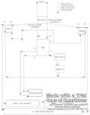
I am in the final stages of building heat treat oven (the one on budgetcastings.com) but am getting a little confused on wiring schematics given the following:

Power: 240 VAC
40 amp SSR (1)
2 BC Kanthal element (connected together)
K type thermocouple from budget castings
PID Power Switch: 22mm Selector (10amp)
Heating Element Switch: 30amp DPST Toggle (used to kill power to elements)
30 amp panel mount fuse/body
Dont plan to use limit switch at this point


Question:

1.) How would adding a second SSR eliminate the the elements being "live" with heat off. (I thought thats what the second switch would do?)
2.) Is my 10 amp selector that is providing just power to the controller sufficient or do I need higher amp for that as well?
3.) Is there way to run both L1 and L2 through controller to act as a "digital" switch to kill both 110v leads when the pause function is initiated unless using the additional SSR performs that function.
4.) Does somebody have a wiring diagram they could send me (for a 240VAC) setup, especially if I get a second SSR, I wouldn't know how to hook it up.

Thanks?
 
If the DPST switch is off, the power is off to the coils. However, if there is only one SSR, when the switch is on, there is 110V to ground in the coils at all times. If you accidentally touch a coil when putting in a blade, while holding the door open with your other hand, you will get a severe shock. That is what the second SSR eliminates.

Adding a limit switch on the door is a good safety feature, and costs less than $5. The DPST switch is still good to have.

One of the forum guys just did this exact build and had a very clear wiring drawing. I'll try to find it later.
http://www.bladeforums.com/forums/showthread.php/927793-Homemade-heat-treat-oven/page3
http://www.bladeforums.com/forums/showthread.php/940049-Electric-Oven-Design-Questions
 
Last edited:
It was on another forum. The drawer is Jim Vaill. The build is very similar to jbblount's.
Here is a copy of the schematic:
 

Attachments

  • HTovensch.jpg
    HTovensch.jpg
    26.8 KB · Views: 42
Any idea where I can find those "$5 limit switches". Only ones I've found are $75 and higher. Would be nice if there was a source for limit switches and toggles, Allied Electronics was high on their limit switches.

Jeff
 
Most of the challenge when using a cheap microswitch is putting together a reliable means of actuating it. Spending more money on someone else's engineering effort can make things easier, but you need to balance your time and skills against the extra cost. As a general rule, switches rated for the full element current tend to be more expensive.

Pretty much any microswitch will get the job done if you are not having to switch the full element current. The one I tend to use is this one

http://uk.rs-online.com/web/p/door-interlock-microswitches/5109348/

mainly because it sorts out all the fiddly bits for me without costing too much; it has a nice simple actuator rod that keeps the switch itself away from the heat radiated off the inside of the door, and it can be over-ridden by pulling the actuator rod out (for checking for hot-spots on the elements, etc).

Unfortunately, I can't find a US source that lists it, but this one on ebay looks like it

http://www.ebay.com/itm/Burgess-Doo...326?pt=LH_DefaultDomain_0&hash=item5190a2fb9e
 
You don't actually switch the coils...you switch the SSRs.

The only place you should need a DPST switch is the Main Power Switch in the incoming power from the plug. As long as it is less than 15 amps per leg, a 15 amp switch will work.
The "Coils Off" switch in the line between the PID and the SSRs is only a SPST switch ( in the wire just before or after the door switch). That wire will then branch to each SSR. This is a low voltage, low current line, and any switch will work.
 
No need for micro switches although they will work to shut down the SSRs. I just got a push button switch at the local hardware store.

Putting a inline fuse on one of the power leads to the PID would be a good idea. A 1 or 2 amp fuse would run the PID. Your total power in should be protected by the breaker box that supplies the wall plug.

If you will look at my drawing for the door sw and toggle switch you will see that they indeed shut off the SSRs as Stacy points out. Maybe you don't actually understand the operation of an SSR it will pass a large power load between L1 and L2 ONLY when there is power to the 2 control terminals. If the door switch or toggle switch is off it shuts down the signal to the SSRs and therefore the elements lose power to both sides.

If you PM me we can get together on the phone and I will help you out.
 
Jim has it worked out well.

The only thing I would disagree with is that any home built device should have independent fusing rated a bit above max draw. The breakers in the wall box could be 50 amp breakers. Terrible things could happen at the HT oven long before the circuit breakers trip.
 
I agree if you are using a breaker that is rate well above the rating of the ovens wiring. When I rewired my shop I put, in 5 20 amp 220 outlets each with its own breaker as well as a 50 amp for my welder. 2 for 2 5hp compressors, heat treat oven, one used by 2 grinders, and 1 for the milling machine. If you have only have a 50 amp outlet I would recommend wiring a small box with a 50 amp plug and wiring inside to a couple 20 amp fuses and a 20 amp outlet mounted on the case then you could use it for a variety of 20 amp devices with no worries. Also if you put 20 amp fuses inside the ovens box you should have a cord capable of handling 50 amps to the fuses.
 
Last edited:
Back
Top