Need a little engineering advise

Mark Williams

Moderator
Joined
Nov 28, 2000
Messages
4,760
I'm putting together a "junkyard hammer" Now I'm not sure what would be the best approach on the pivot point. Should I set it up as in the drawing or move the motor to the back and pivot in the middle. The head weighs 35 lbs, anvil weighs 125 lbs.
 
I think the middle would be about right.
You have a trade off between stroke length, which will affect how much force the hammer has coming down, and strain on the motor.
As you move the motor and lift arm closer to the load and away from the fulcrum/pivot you get less leverage against it.
As you move the lift arm and motor closer to the fulcrum/pivot you get a longer travel as the hammer moves up and down due to increased arc length. Longer travel should let it get to moving faster and give you more power.

I suppose maybe move it as far back as your motor has power to cycle it :confused: 
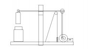
The middle seems like it would be a good compromise on the two.
I really don't know much about power hammers though :confused:
 
Thanks Matt, You confirmed pretty much what I was afraid of. I'm hoping that the power coming from a 2hp gearmotor at 20:1 ratio, will help overcome the downhill side of the stroke. I almost have to put the pivot in the middle :( , now that I look at it. In order to have a cushion of space for various work thicknesses, I'll need the shock in the system. It wouldnt work correctly in the middle. I guess it is give and take. ;)
 
I think I mis-understood.
I thought you were asking about moving the motor left to right in your drawing and keeping the hammer arm pivot where it is in the drawing.

Now that I read your second post, I agree....put the hammer arm pivot in the middle and have the motor on the opposite side of the pivot as the hammer. This will limit the hammer travel a little bit compared to the other way, but I don't think that will be much of a problem. It will also give the motor and hammer equal leverage which should help alot on power concerns.
I bet the shock could still go in the middle though, on an angle from the upright to the hammer arm as long as its free to pivot at both ends. I'll have to think on that a little bit.
 
Here's another idea Mark
How about rather than the shock, a chain with a big ass coil spring in it? Put it on the back side between the motor and the pivot to act as a cushion/stop on the downstroke. Or better still, a cable on a pulley with coil springs, similar to a compound bow. That way you don't have any slack to deal with on the upstroke.

attachment.php


Does that make sense? I'm really not sure how the whole thing works beyond the basic concept of the wobbler and lift arm moving the hammer.
 

Attachments

  • hammer.JPG
    hammer.JPG
    9.4 KB · Views: 204
Hmmmm. Now that make a lot of sense. The way it sits right now I can still go any direction with it. It's still just an anvil with a hammer sitting on it :). I'll look at the junkyard tommorow and see if I can find some railing with evenly spaced holes. I can weld the railing across the bottom of the pivot bar and the along the bottom, that way I can adjust my spacing and pivot ratio. That's the plan anyway.
 
This is going to be one of those "cant get my brain to shut up" nights. I'll be draggin butt tomorrow :)
 
Mark,Two things here.First do a google on "Junk yard hammer" ,there are several detailed construction plans,and technical info on finding the harmonic spot in the arm.Second,the placement of the pivot,recoil spring/counter weight,and lift arm are VERY critical. Which leads us to the fact that the base and support arm you have will turn that thing into a 400 pound jack rabbit jumpin' all over your shop.It could easily kill you.Read up on it before you go any farther.The trip hammer system in your sketch is not going to work.You would need a harmonic arm made from two trailer leaf springs.
The best JYH I've seen yet was made from a truck rear end and was driven by a 1HP motor.The emergency brake cable started and stopped the hammer.The drop arm was a HD shock absorber,hammer and anvil were RR track.I think Keenjunk.com has the plans and several links. - Stacy
 
Mark you could also look into the bradley hammers from the turn of the last century. They are a horizontal hammer. http://www.anvilfire.com/power/bradley/pauls.htm
that has some pictures, but it is missing a wooden beam that runs from the hammer back across the pivot point to a conecting rod. They also made a model that had a steel beam that was attached to the hammer with a heavy canvas strap. This provided most of the shock absorbtion since the arm is only lifting the hammer then letting it fall.

WS

PS I'm glad to see you working on a way to not have to hand forge some of those monsters you've been making.
 
I think between the rubber bumpers and the shock absorber, I will have enough damping in the system to where it shouldn't be too dangerous. I'll beef up the pivot arm and add some safety straps here and there. With the 20:1 ratio I will end up with 87 BPM. What is the highest BPM of a little giant 60 ?

here's a new drawing.
 
Just got home from the junkyard. I'm up to 255 lbs of crap so far not counting the gearmotor. My hope is to keep this under 400 lbs.More progress pics later. :)
 
Did you pick up a broom?

JUst yanking your chain. Looks like progress to me! What kind of mig welder do you have?
 
Mark: That looks really cool. I hope it work out, but just in case it don't could you have someone take a video of that sucker when you start it up. :D :D
 
B,

If you lookat the picture in the third post of this thread, you will clearly see there is a broom laying on the floor........with a lot of dust on it. I'll get my neighbor to take a video I.G. Maybe some of the money from the funniest videos people can go towards my hospital bill.
 
Yep!! That is exactly what I was thinking. I can picture that sucker walking down your driveway and you trying to catch it. :eek: :eek: And you yelling ya'll come back h'er :D
 
Thats looking really good Mark
I'm starting to understand how they work a little better too. I see why you need the shock on the lift arm, saves the motor :D I guess since I quit the whole engineering thing I shoulda stayed outa this thread :eek:

I started to do the math to figure out how much power you'd actually need to run that thing since you were worried about the motor. I couldn't find the right equations in my old physics book though and by the time we got to wave motion I was pretty good at sleeping through lectures :footinmou
I thought I could set up the equation myself but when you start trying to add gravity as a damping force and then convert all the stuff on the oscillation into torque it just makes my head hurt. My philosophy on things like this is that trial and error is much less painful. (Its also the reason I have over 500ft of extensions cords ;) :D )

I suppose its probably too late, but the more I think about this the more I think I would make an adjustable anvil. If you can move the anvil up and down you can work on any thickness material you want without sacrificing hammer travel. That way when your first trying to draw out a billet and want to move alot of material you still get full power. Maybe thats not as much of an issue as I'm thinking, but I thought I'd throw it out there along with my other bad ideas :D
 
HahAAA!! You're too much. I love it! Looks good My Man :D :D
 
Back
Top