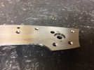
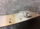
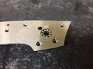
Persian linerlock WIP.

Joined
Jan 11, 2009
Messages
35
Hi all.

I have been mostly a lurker as of late and have been primarily using the forum as a research tool and knowledge base. I feel as tho I have gotten to a place now where I can give something back and I figured a work in progress thread would be just the thing. A hearty thanks to all of the knowledgeable people who give so freely so that others can learn!


This is my 3rd attempt as a custom folder so feel free to let me know if there is a better way of doing things!

The reason for doing a liner lock is so that I can have most of the screws hidden. I also use the liner to make a bearing pocket and then bolt a hardened plate on on top of that which is then covered up by the bolster. I call it my OCD bearing design :D. I don't know if it really solves a problem or not but my hope is that for people who are interested in the knife that they will be able to appreciate all the work put into it.

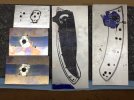
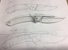
The top drawing is the initial drawing (by GD Clark) that "we" did to get the flow and concept of the knife fleshed out. You can see the pin holes drawn on it so that we could have a reference point for making a plexiglass model. The knife was drawn on grid paper for 3 reasons. One was that there needed to be a clear horizontal reference. I have wasted way to much time trying to modify a knife that wasn't working and getting stuck because I lost track of where level was. The the other reason was so that I would have a 0.0 reference point to use calipers to measure points for the digital readout on the mill. Lastly, by having a true vertical plane it lets me use a jig for cutting the lockbar, cutting the lockface, and drilling the detent hole's in the liner and the blade.

The plexiglass models purpose is to flesh out how it will feel in the hand and to also make sure the folder will function. Things like detent travel path are really easy to see this way. You can also try several different locations easily by using a felt tip pen. It is also very fast to shape and it doesn't make any dust that you have to worry about breathing.

The last drawing is the final version and has all of the hole locations for the build on it. As you can see it was slimmed down a fair bit. We hadn't planned on it initially but adding a spot to put your index finger ahead of the flipper tab feels really good! It makes it easier for EDC type tasks and when used as a fighter it really made it feel quick. I expect it to be fairly light in hand when it is done as well. The last major difference between the initial drawing and the final drawing was in the shape at the back of the handle. Having it more rounded made for a way better fit for people with bigger hands. GD has small hands and didn't really notice any problems but my pinky came down right on top of the raised part. By rounding it off it also made the back of the knife disappear into the hand better which gives it a really aggressive feel.

IMG_0159.JPG


Matt
 
Last edited:
Ok, so the design phase is done. Or so I thought! I ran in to a little snag involving the pivot design and the right amount of travel for the pivot pin slot. This was also one of those day where you spend about half your time making stupid mistakes. The only positive thing is that I found a few things that I was doing right unintentionally. Now I am doing them right intentionally! ;)

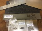
Time to take stock of the inventory. I have the titanium for the liner, bolsters, and pocket clip. Then there is the carbon fiber for the scales followed up by assorted screws, pins, and the pivot. I need to order some more stop pins in the correct size and some more flat head screws.
IMG_0160.JPG

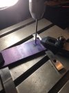
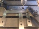
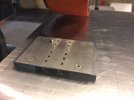
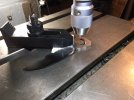
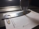
Now it is time to start in on the blade. After a trip through the surface grinder it is time to get it clamped down on the mill. Here we have the pivot hole center drilled, drilled, then reamed to .1560 in. That is the size of the pins that I am using for the stop pin and rear alignment pin. The reason for having the hole reamed is so that it will line up in the jig perfectly when I am ready to drill it after heat treating. I can also line up the carbide tipped drill bit using the same size pin in the drill press chuck. You will also noticed that I only surface ground the bottom of the blade steal. After the blade is profiled I will get it close to the final thickness I want on the surface grinder so there is no reason to clean it up when I will be surface grinding it again soon. It also makes it easier to do the roughing as I don't have to tape the bottom side to protect it from scratches. This also happens to be the side the the burs will be created on while roughing it out with the belt sander so we are saving time removing the burs as well.
IMG_0164.JPG


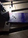
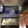
Up next I have punched the holes for the start and stop of the pivot pin slot. The relationship of these two points has caused me some serious head scratching over the past couple of days as I was trying to figure out why I was having some layout problems. Normally I can poke the pivot hole then move to the stop pin hole and drill it, then rotate the rotary table the correct number of degrees and I am done (overly simplified description I know)! This time I had to offset the stop pin hole 20 degrees before I drilled it so that the top of the blade would line up with the top of the bolster and the bottom of the bolster when closed. If this was designed on CAD and done with CNC I would have never noticed the problem but I did a precise drawing on paper and marked the hole positions with a digital caliper. This ment that I didn't really know the exact position for the stop pin slot which I usually find by trial and error.

The source of the problem is that this blade is not actually pointing straight ahead! It is in fact pointing down at 20 degrees or so. The reason for this is because of the curving nature of the Persian style. My previous build had been a more traditional EDC design where everything is on the same plane. The hard part for me was figuring out why I needed the offset of 20 degrees. I would ask myself "if I cut a 154 degree arc what does it matter where I start from?" I just use my template and mark it where I want it! The trick was in realizing that it is about WHERE the arc is located in relation to the pivot pin. When you make a blade that is in line with a horizontal plane you can start from the stop pin hole and cut the arc with no other considerations. If the blade is pointed any other direction then you are going to need to make some adjustments.

IMG_0167.JPG

Here is a video of me finish milling the stop pin slot. https://www.instagram.com/p/BMI0NUcA9AK/

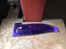
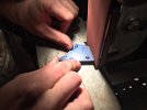
And lastly for the day is bluing and tracing the template on the blade material, cutting it out with the bandsaw, and rough sanding it to a slightly oversized shape.
IMG_0170.JPGIMG_0171.JPG
 
Last edited:
Pavlos,

Thanks for the interest! Things have stalled a bit on the build because the titanium for the liners is warped. The new material should be in on Monday :D.

I had considered trying to straighten in but I only had .010 or so to spare in extra thickness so there really is no practical way to use it for the liners. I can use it for the plates to mount in the scales for the hidden hardware tho so it isn't a complete loss.
 
Ok I finally made some progress this week.

On the liner the holes were center drilled then drilled. Two of the holes were reamed for pins and then lastly the bearing pocket was drilled out. The screw holes for the scales and bolsters were chamfered for two reasons. One was so that they would be flush with the liner. The other and more important reason is that it provides a method to get precise alignment. This allows the bolster and scales to align back up with minimal fuss whenever the knife is fully disassembled. Using the digital readout on the mill allows for precise depth control and also perfectly centering the chamfer to the chosen hole locations. The four screw holes that are not chamfered are for the back spacer. We decided to make those visible for aesthetic reasons.

IMG_0191.JPG

Next up is the bolsters. The bearing pocket was milled out then the holes were drilled .08 deep then tapped for 2-56 screws using a tap-o-matic. To mill out the bearing pocket you will notice that I used 3 different sizes of end mills. I only had to make 2 actual milling movements because I used the larger 25/64 and 5/8 endmills to simply "drill down" to the depth I want.

IMG_0205.jpg IMG_0215.JPG


Lastly, here is a pic of all the current pieces. I can't grind the blade yet because of all the interactions with the handle. The top of the blade will be flush with the top and bottom of the bolster and the grind line will mirror the bottom of the handle. The next step will be to shape the bolsters and mount the scales then finish getting the final shape of the handles. You will also notice the bearing plates. They are hardened and waiting for me to drill out then ream the pivot hole after one more trip through the surface grinder. After that they get shaped as well.

IMG_0214.JPG
 
Last edited:
I have gotten a lot done!

First thing I had to do was modify the screws to fit in the blind holes. I made up a jig so that all I have to do it get it close on the belt sander then hit it really quick on the surface grinder.

IMG_0217.JPG
 
Next up was to get the scales mounted to the bolster.

To get the shape of the bolsters to match I went ahead and made a jig for it. All in all it is not a huge waste of time as it can be used for similar knives of this type. Here is a pic of GD getting the bolster mounted below the jig down to shape. He is also getting the front of the jig to the proper shape as well.

IMG_0225.JPG

Once the bolster is shaped it is time to get the carbon fiber shaped to the bolster. It helps to scribe the bolster arc on the carbon fiber then once you have good skills on a variable speed grinder you will find that you are not too far off. It takes some patience but once you get the hang of it it will take less than a half hour to get a really good fit. The pics show the mounting bar that I made screwed down to the liner with the bolsters attached. I then milled out a pocket in the carbon fiber. After it is fit correctly then I epoxy it into place. By doing it in this order you will be able to take it apart and repeatably get it back together while maintaining a good fit.

IMG_0223.JPGIMG_0221(1).JPGhttps://www.instagram.com/p/BNGO_GsgNB9/?taken-by=matt_lyon_custom_knives

I realized I didn't take a pic of the finished scale so it will be in a later post.
 
Last edited:
This is the last update before the holiday!

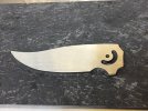
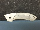
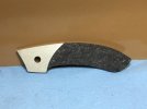
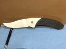
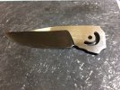
Here is a pic of the handle. It is pretty close to it's final size and shape. There are a couple of minor adjustments to be made but overall it is turning out pretty good. I also decided to see how it will look with the blade in it so here is an early sneak peek!

IMG_0229.JPGIMG_0227.JPG
 
Last edited:
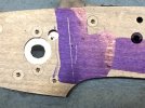
I decided to make a fairly significant change. I was going to have 4 screws showing in the carbon fiber that would bolt into the back spacer but after looking at it for a bit I just couldn't do it so the only visible fastener will be the pivot. So I made the modifications to the liner and got the back spacer and blade shaped. I am pretty pleased with a happy little accident of being able to have the flipper tab hidden when the blade is open. Now I am off to the grinder!


IMG_0240.JPG
 
The blade is hardened now. Time for some tempering and cryo. It came out to 63.5 RC which is right were it should be for CPM S30V. The reason for checking the hardness is to make sure the heat treating was done correctly.
IMG_0253.JPG

I also got the handle fully assembled. Here is a video of it. https://www.instagram.com/p/BNz2Hy6gyab/ There are 20 screws currently in the handle. The total will be 26 once the bearing plates are in and the pocket clip is mounted.

I had to make a special tool to get in between the liners to tighten the two screws that hold on the scale. I bought several torx bits and drilled an appropriate sized hole. The hole is slightly undersized so that it has to be pressed in. Next I soldered it in place then used a cutoff wheel to cut it off close to flush before I went over to the grinder and smoothed it all out.
 
Last edited:
I think it's an excellent build, very clean.

I don't have an instagram account so couldn't watch your video.

Nice tutorial for me to keep bookmarked and use future-wise.

Paul
 
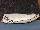
Next up is getting the blade ground. To help get a centered grind I would recommend a height gauge. You could use the cheaper options of having a scribe on a rod that mounts in a flat piece of metal but it is really limited. With a height gauge you get precise adjustments and the tip you use to scribe with is excellent! If you are having problems with centering the blade tip in your folders this would be an area you may want to explore.

IMG_0257.JPGIMG_0259.JPG As you can see in this pic my scribe line is not perfectly centered. This is from the surface grinding after heat treating. I went about getting it centered in 2 ways. One was obviously by grinding more on the side that was thicker. The other way to move the center is on the surface grinder. By making the overall thickness of the blade thinner and only taking off from one side it will move it in the direction you want.

IMG_0261.JPG Ready for some hand sanding now!
 
Last edited:
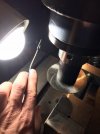
After heat treating and surface grinding it flat again it is time to punch out the pivot pin. Even tho warpage is minimal, to get a perfectly perpendicular pivot hole you need to do it after heat treating. I drill and ream the initial pivot hole the same size as my stop pin. This allows me to chuck up one of the pins and use it to get nearly perfect alignment. I feed the pin in the hole, clamp it down then drill and ream it out to 3/16. I use a 4.5mm carbide tipped drill bit and a carbide 3/16 reamer. The reason for using a 4.5mm drill bit is because of the cost. It was a fairly common size close to what I was looking for in diameter. Also using a carbide tipped drill bit vs a full carbide drill bit will save you a bunch of money as well. I thing the one I am using is $15. I remember hearing/reading something that carbide does not like to cut slow so I attack it pretty aggressively as far as speeds and feeds go. I go by feel but looking up a recommenced speed and feed will give you an idea of how fast you should be going which will help the drill bits last longer. I am not too concerned about drill bit life but the carbide reamer cost way more!

IMG_0260.JPG
 
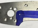
It was kind of complicated getting all of the screws counter sunk correctly. What made it more difficult was having screws coming from both sides of the liners. Once the liners get below about .058 in. you have to start taking off from the screw heads to get them flush with the liner or counter sink them deeper and then also countersink the threaded hole as well. If I was using thicker material this wouldn't matter much but I am going into a .080 blind hole and I can't afford to give up any more threads.

On the blade side of the liner the holes were countersunk to the max that I could get away with then I had to take off about .006 of the heads. On the out side going into the back spacer I had plenty of room so I countersunk deeper and then countersunk the threads in the liner since that is where I had room to spare. Here is a pic of touching up the depths with the countersink. Having a digital readout on the z-axis is sooooo nice :D

IMG_0275.JPG
 
So, now we get to the bearings. I am calling this my OCD bearing design. I don't know if anybody is doing anything like this or not but I suspect not. It is a fair bit more work and adds more parts to the build so it is defiantly not used in any type of production and unless you like adding complexity making it would be a hair pulling experience. In defense of the idea I would say that if simplicity was the only path then we would all be wearing solid state timex watches!

Here are some pics.

IMG_0276.JPGIMG_0277.JPGIMG_0278.JPG

What I am doing is taking some of the blade material, milling it down to thickness, drilling the holes (2 mounting screws, piviot pin hole, and stop pin hole.), heattreating it, surface grinding it, then shaping it. (There are a few more steps but you should get the gist :D)

What this does is allow me to have all of the bearing surfaces surface ground and hardened (2 plates and the blade). The pivot pin bolts also clamp directly to the plate so the bearing preload is placed directly onto the bearing surfaces. I am not saying that other designs are inferior but for a non CNC build and fully hand made it is inherently parallel to it's self.

To adjust the distance between the blade and liner I simply surface grind the liner thinner to increase the clearance.

This also allows for an easy way to have the pivot bolt heads countersunk in the bolsters.
 
Last edited:
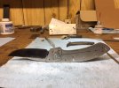
Here is a look at the current state of the build.

IMG_0280.JPG The liner is all cleaned up and all of the fitting of the scales, bolsters, and liner/backspacer is done.

IMG_0281.JPG Here it is assembled. The handles are still a bit over thick and the shape of the spine need to be adjusted but overall I am pleased with its current state. Up next is getting the final shaping done so that I can do the lockbar/lock face/detent.
 
Last edited:
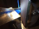
OK, time for this weeks updates!

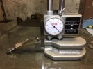
The main thing I was working on was getting the locking mechanism functioning. When I designed it I made sure that the detent travel path would stay on the blade but now I had to translate that from a pretty accurate drawing to the actual knife. I spent a fair bit of time with a digital caliper and layout fluid to make sure it was all going to work. Then I marked a line that was close to where it needed to be on the blade and ground down to it on the belt sander.

IMG_0319.JPG

This is the most important dimension when planning where the detent is going to travel so make sure you get it right!

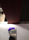
After getting the lock face close it was time to put a 7 degree angle on it and finish moving it in some more. I use a tool post grinder with a home made sanding belt attachment for my surface grinding. To do the lock face I put a stone on it and rotate the head 7 degrees. To make the cut I lock the bed in place and make chopping motions with the stone and take off .004 inch per cut. https://www.instagram.com/p/BKEAP53jBNF/?taken-by=matt_lyon_custom_knives That is a different blade but the process is the same. I like to use a jig to mount the blade in a machinists vice, but as I mentioned earlier, the blade is at a 20 degree offset so my jig for a horizontal blade didn't work. Another thing to consider is that because the blade is at a 20 degree offset and the whole knife is one big flowing arch you don't actually hold it at the plane in which I drew it on the paper. I wanted to have the lock face be vertical when it was held in the hand and that turned out to be 9 degrees so I made a jig on my rotary table with that much offset. I also use that same jig to mount the liner and blade when doing the detent.

After the lock face is cut I scribed a line on the liner and did some more double checking with calipers to make sure it was all going to work.

IMG_0322.JPG

As you can see in the pic the higher up you go the more room you have to place the detent ball. The balancing act is figuring out how much to actually cut the scale. While it would be convenient to have the detent ball near the height of the pivot, nobody wants a lock bar that big or would like the idea that the liner had a cut through half it's width!

IMG_0325.JPG

Next up is drilling the stop holes for the jewelers saw. The thing to remember is that you want to cut up to the line. So you have to place the stop holes above the lines!
 
Last edited:
For those paying close attention in the second post you will have noticed that the two liners are different! That is because I ruined the first one cutting the lock bar!

IMG_0324.JPG

I wasn't paying attention to the direction of the saw and the direction I was cutting. Think basic grinder saftey..... I should have been grinding on the other side of the liner!

I mount up the liner in a machinists vice and just eye ball it to set the proper position. It ripped it out of my hand and when it fell to the floor it bent it! I can't believe the amount of force that it took to do that! Here is a pic with the lock bar cut.

IMG_0330.JPG

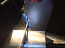
To get the face put on the lock bar I actually came up with something that is controllable and repeatable. My other attempts have been lacking up to this point and have had results less than ideal. First some theory. The lock face on the blade is 7 degrees. If the lock face on the liners is square to the liner only a sliver of it would contact the blade. This would cause it to "wear in" very quickly and most likely result in having too much travel across the lock face of the blade. You also want the part farthest away from the pivot to make contact first. This will help you avoid lock rock.

I mounted the liner in the machinists vice again and held the lock bar out with a shim (allen wrench wrapped in tape). Next I set the correct vertical angle and clamped it in place. Then I set the angle offset for the face on the liner by moving the position of the vice relative to the platen. I used a new 400 grit belt and then pressed the liner against the platen with a very moderate force. I then had my friend turn the belt sander by hand! It took a surprisingly short amount of time to get it where it needed to be! I also use a marker on the face so that whenever we reset after testing it I could be sure that it had a consistent and even cut.

IMG_0326.JPG IMG_0329.JPG
 
Last edited:
Back
Top