PID forge upgrade (videos added)

If you crank the blower down too much and cut the gas to a bare flow the burner will sputter, and may go out, but flash-back isn't an issue with a blown burner.

Not sure if the above needs any clarification, but I will add (as a warning) that if there is gas flow without the blower on, there is serious risk of flash-back.

I know this from experience, when, years ago, I once shut the forge down, (first gas, then blower) then decided I wanted to do one more heat, and turned the gas back on before the blower, and in the time it took me to plug the blower back in, got a surprising "pop" that blew the baffle off the blower and increased my heartrate by about 300%. I'll never do that again:rolleyes:.
 
how large a feed pipe can you go to before you are close to that "edge"?
I don't know of an answer, but in all the shops, schools and all the blacksmithing conferences I've been to, I've never seen anything larger than 1/2" pipe used for the gas supply lines. Even in our mentoring center where we have 8 forges plumbed up and often running at the same time. So I'll answer your question with a question: How large of a pipe do you want?
 
I don't know of an answer, but in all the shops, schools and all the blacksmithing conferences I've been to, I've never seen anything larger than 1/2" pipe used for the gas supply lines. Even in our mentoring center where we have 8 forges plumbed up and often running at the same time. So I'll answer your question with a question: How large of a pipe do you want?
I dont personally really want any specific size - I was thinking more in terms of future guidance for someone in the future who might read this thread (plus just curiosity on my part). sound like experience reigns here - and dont use anything larger than 1/2".....
 
I don't personally really want any specific size - I was thinking more in terms of future guidance for someone in the future who might read this thread (plus just curiosity on my part).
I figured as much...
sound like experience reigns here - and don't use anything larger than 1/2".....
I'm not sure I'd use that as the gospel truth, but I'd be curious to what others have to say on this. Part of the reason could be because of cost, or what was readily available, not to mention added weight of larger sized pipe. I'd guess that if someone had a bunch of 3/4" or 1" pipe they wanted to use, then that would be fine.
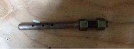
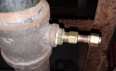
One piece that might be missing in your thought process, Cush, is that the propane isn't just plumbed into the air line with the 1/2" (or 3/4", 1" etc) pipe. There's a copper nipple with holes for the propane exit that is inserted into the mixing tube. (see pics)
20200120_171316.jpg
20200120_171248.jpg
 
I have never used a pipe with holes to inject the gas. I just plumb a 1/4" nipple to the side of the Tee. No orifice is needed with a blown burner. However, there is nothing wrong with your setup as long as the holes are large enough.
 
One piece that might be missing in your thought process, Cush, is that the propane isn't just plumbed into the air line with the 1/2" (or 3/4", 1" etc) pipe. There's a copper nipple with holes for the propane exit that is inserted into the mixing tube.
Honestly, I am not sure whether using that nipple with holes will make a difference or not with regard to blow back - though stacy's observation that the rig can be plumbed with just a plain old "T" is a hint that it does not make a big difference. I do think that it certainly can not hurt - you will get the best flame if the air and propane are thoroughly mixed before they enter the forge proper. Whether Stacy's "T" fitting or your nipple with holes have a difference in that amount of mixing depends a lot on how the air is flowing in that feed tube - I dont know enough about that flow to guess one way or another right now...
 
Thanks, guys, but I bought this burner/nipple combination from Pine Ridge Burners on recommendation from a few professional blacksmiths I used to live near (Darryl Nelson to name one) and have been using it for the past 7-8 years without any problems. So while you may be correct that other designs might work just as well, please don't continue to question this set-up.

PS- I just went to the Pine Ridge website and see (a) they are now using a different air/gas mixer assembly that's similar to what Stacy was describing, and (b) they also sell an air pressure switch that looks like it addresses my concerns about shutting off gas solenoid if no air flow....I may have to buy that.
 
Last edited:
WEO - my sincere apologies if I gave the impression I was questioning your setup - I was not intending to do so. I tried to say the injection nipple you are/have been using certainly could not hurt - might actually help a lot in terms of mixing of the gas and air - I just do not know enough to say. Certainly there is no reason at all to go away from the setup that has been working for you for years....

Again - apologies if it seemed I was questioning something :-(
 
WEO - my sincere apologies if I gave the impression I was questioning your setup - ...
Again - apologies if it seemed I was questioning something :-(

Cush - No need to apologize. Hopefully you know me well enough by now to know that I'm not that easily offended.

My post was merely intended to point out that this set-up works, so that in the future, others (with less confidence in their own judgement) who read this won't feel that they need to change something they don't need to change.
 
There are many ways of mixing the gas and air. Yours is one of them. An expansion (mixing) chamber is another that I recommend. Some folks make a loose fitting twisted metal piece to put in the burner tube to swirl the gas and air as it enters the chamber.

If you use an expansion clamber in the burner, place it just before the burner tube and have it around 1" larger than the manifold pipe. For example: 2" manifold pipe-3" expansion chamber around 4" long - 1" burner tube.
 
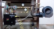
Good evening, all. Here's the progress from this week. I've got everything plumbed in (except the propane tank), wired up and just now plugged it in and flipped the power switch on. No sparks:D! The main NC valve clicked open, the blower started, and when I turned the high flow switch to 'ON', that valve clicked open, and clicked shut when turned back to off. Nothing happened when I turned it to 'AUTO', but I'm not sure if that's something I need to worry about yet because I haven't done anything to program the PID. 20200124_181600.jpg

Should I worry about that or is it time to hook it up to the tank and fire it up?
 
Last edited:
One thing at a time. I would try running it on manual at first, and makesure all is running correctly before you eventry turning it over to the pid controller
 
One comment, but maybe I'm not seeing the piping clearly. It looks like the pressure gauges are on the downstream side of the needle valve? If so, you won't really get much pressure at all since there is no restriction from pressure gauge to injection point. The pressure gauge should be upstream of the needle valves in order to read adjusting pressure from regulator.
 
Hi Ken, you are seeing that correctly, and I do have a gauge at the regulator on the tank. I put those in because I was thinking it would give me an idea on the flow and where to re-set the needle valves if they were to get adjusted for some reason. But now that you mention it, that would need a flow gauge, not a pressure gauge:confused::(... While not useful, they aren't dangerous, are they?

Good morning, Cush. That's the plan, but on my morning walk with the pup, I thought I'd play with the PID before hooking up the propane, both to check the valve and to learn how to program the thing. I don't think it should care whether it's set for 50-60 degrees or 2000 degrees.
 
Sounds good. You know i am not a fan of running pid’s on auto tune ... but is worth a try. If it does not settle in, i would first try a proportional band of ... say 10-15 degrees. If it still seems to be behaving weird, trya proportional band of one degree, then zero as a last resort. I would not use either the integral or differential functions ... the wide open forge is, i think, too uncontrolled an environment (relatively speaking) for the fine lvel of control they are intended to supply...
 
Naw, the location of the pressure gauges is not dangerous at all. It will be interesting to see what reading you actually get on them. I'd expect in the ounces range, when you light it off will tell what the actual reading is in that location.

I agree with Cushing, run in manual, get forge burning nicely and able to control flame by adjusting needle valves. Then try auto for the pid to do the controlling. Comment: I'd think at ambient temp the solenoids would open when switch is moved to "auto" since the pid controller should be calling for heat at that point. You might double check your wiring for auto mode? I have NEVER tried a pid for forge control so do take anything I might say about pid forge control with caution {g}
 
You might also try reversing the polarity on your thermocouple, as a test. I wired mine up the wrong way and the PID just wouldn't turn on.
 
I just ran a "test" and something isn't wired right, so I have a few more questions:

First off, I noticed that ASCO NC valves got warm as they were opened. I think this is normal because of the current running through them to keep them open, but just checking if this is somethin

You might also try reversing the polarity on your thermocouple, as a test. I wired mine up the wrong way and the PID just wouldn't turn on.
Thanks for the suggestion, but I don't think it's the thermocouple, because it seemed to read the temp correctly. (According to the instruction manual, if one wires the thermocouple backwards, the reading will go down as the temp increases.)

Here's what I did for a test: I used a space heater in the forge to modify the temps to see if I could get the high flow valve to click on/off when on AUTO. The temp in the garage this morning was 51 degrees. Following the instruction manual, I set the following parameters:

Proportional Constant : 0.1 (Type K control range is 1500 C, so 0.1 should be 1.5 C or 2.7 F)
Integral time : 2 sec
Derivative time: 20 sec (factory setting)
Damp constant: 0.2 (factory setting)
Cycle rate: 2 sec (factory setting)
Digital filter: 0 (factory setting)
Target Temp: 65

I turned the space heater on and the temp got up to 100deg and nothing happened with high flow valve. I then put the thermocouple between a couple of ice pack to get it back down to 50 degrees, and still nothing.

In the alarm setting instructions, it says: "The J1 relay is controlled by parameters AH1 and AL1 and the J2 relay is controlled by parameter AH2 and AL2." Also the terminal wiring diagram says that J1 terminals are 3,4,5 and the J2 terminals are 11, 13, 14. I have nothing connected to either of these, and think that's the problem, but I'd like some input before re-wiring.
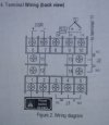
20200125_113828.jpg
If you look back to the wiring diagram, I have the DPDT wired to the SSR which is what I was told, (that didn't and still doesn't make sense to me) but I'm wondering if this should be connected to the J1 terminals...
 
Confirmed the dpdt should be hooked up to the SSR. I need to get home to check the manual ... but if the “relay” outputs are higher voltage outputs intended to hook up to a mechanical relay, then they are and should be unused in this case (as long as it is correctly wired to an SSR-dedicated output

Does the pid display have any indication of the the output being “on” or “off”?
 
Back
Top