PID Timer Controlled Tempering (Toaster) Oven WIP

KnuckleDownKnives

Time to make the doughnuts..
Joined
Feb 12, 2015
Messages
1,715
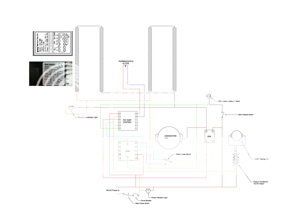
I have half of my parts for the build, the PID, SSR thermocouple and oven. I need to get the timer, switches, lights and a breaker. I am adding a selector switch so I can take the timer in and out of the circuit for warm up since I am going to take some 3/8" flat bar I have to put on the shelf to help prevent temperature swing. It's going to be a 3 sided box with the front open to insert the blase in. I'm going to drill a hole in the end of the flat bar to insert the end of the thermocouple in. I've read with this design i should get very even temps. I may incorporate an alarm on the system at a later date.

Hopefully someone can take a look at my wiring diagram and see if I have it right. If I don't use the timer it's straight forward, but I have had a hard time finding a diagram with both PID and timer. Essentially what will happen is the PID will control the hot side of the AC input to the elements and the timer control will control the neutral side of the elements which will allow either one to interrupt their voltage. The oven is a convection type oven and the fan will be controlled with the PID control. If you think it would be better to leave it on constantly when the oven is at temp please comment. I have gone back and forth over it and not sure.


20150801_110335_zpsykzuw5ut.jpg

images.png

Edit: This is the final updated schematic.

 
Last edited:
I don't understand the timer. It appears to have no relay connections? I can't see what it is hooked up to do.
 
I don't understand the timer. It appears to have no relay connections? I can't see what it is hooked up to do.

Apparently I have something wrong which I figured I did. I want to have a temp control and a timer. The temp control doesn't have a timer. I want to incorporate a timer. I can't find a diagram that has both temp control and timer. I have seen plenty of images of deferment units utilizing a temp control and timer but now diagram on how it's wired. What I have is a best guess.

What is the purpose of a timer? Your PID will have timer functions built in

The temp control pid doesn't have a timer.
 
Last edited:
What type of toaster oven do you have? Most toaster ovens have a built in timer, and my toaster oven (old simple type) has an "ON" position where the oven stays on and bypasses the timer. I took the simple way out and mounted TC thru back of toaster oven positioned just above the brick on rack where blades lay.The PID is mounted inside a box with a recept mounted in box and just plug toaster oven to recept for PID control. With plug connectors on TC, it allows me to move PID box from lead melting pot for bullet casting.

I've not seen a PID controller with a built in timer function, and the "MyPin" temperature controller you have surely doesn't have an internal timer.

Your wiring diagram looks a bit complex for what you need, unless you've got a toaster oven with all controls missing and only the elements.

Later
 
Ken you're right, it is a little complex. I want to do away with all of the original controls and put my own in. Part of the fun of it for me. My other hobby. I have just as much enjoyment from building the equipment as I do making knives. Plus the original timer is only good for an hour and I like buttons. :D
 
Put the timer in the path between the PID and SSR. One of the wires from the PID to the SSR goes on the relay contacts ( 11 & 12). The timer will then turn on the SSR and shut it off.
 
Stacy's got the right location for the timer. That's a low current spot and easy to control. If you like making things, did you consider using an Arduino for the control, PID part and all? built in time and PID control :)
 
Stacy Thanks for the input. I thought I needed to do something like this, I just couldn't figure it out. Please take a look at the updated schematic and let me know if I got it right please.


Edit: This is the updated schematic.


Last edited:
Stacy's got the right location for the timer. That's a low current spot and easy to control. If you like making things, did you consider using an Arduino for the control, PID part and all? built in time and PID control :)

No, I had not thought of that. Maybe a project for the future. I still need to build a forge and want to do temp control on it, maybe I'l look into the Arduino for that.
 
From what I can tell, your drawing looks good to go. You've got the fan cycling with the heating elements?

Sounds like you've worked with Arduinos before? Do you use the whole Arduino in a project? OR, just the uC chip on a PCB to incorporate the uC as part of the total project? That's how I normally use Arduinos, work up the code, compile, load to Arduino, then move uC chip to project board.

Good luck with the oven,

Ken H>

The fan, yes. I questioned about that in my OP, wasn't sure if it was better to leave it on with constant power or cycle it with the elements. What is your take on that? Cycle it or leave it constant?

No I have never used one before, but have read a little (very little) about them and seen some things others have used them for. There are enough web resources out their t where it wouldn't be to hard to figure out.

Note: I am updating the original post #1 with the updated schematic.
 
Marc, I don't really know the pro vs con of leaving the fan on all the time. My toaster oven (factory controls) cycles the fan with the heating coils. It seemed to me like the fan should run all the time, but the fan is only to circulate the heat from coils for even heating. When the coils are off, there is no heat to circulate.... I guess. I just don't have an answer, but will be looking for other input to this question. Stacy should chime in - he's always a GREAT source of knowledge.

Ken H>
 
I think it is simpler to have the fan on during the heat cycles.

Your re-drawn schematic looks good with one change still needed.

The indicator lamp for the "Heat On" mode should be between the SSR out line and the power lead drawn below it. That will make it run in parallel with the heater coils. As drawn it is in series with them, which would run the entire amperage of the coils through the lamp. It would act as a fuse and blow immediately. Same goes for the one to indicate "Power On". It should be parallel between the two power leads, not in series with one of them.

Recently, another member made this error and his unit kept blowing the light and not running. I missed the problem in the schematic at that time, but saw it on a later view. Indicator lamps are easily just looked past since they are passive devices.
 
I think it is simpler to have the fan on during the heat cycles.

Your re-drawn schematic looks good with one change still needed.

The indicator lamp for the "Heat On" mode should be between the SSR out line and the power lead drawn below it. That will make it run in parallel with the heater coils. As drawn it is in series with them, which would run the entire amperage of the coils through the lamp. It would act as a fuse and blow immediately. Same goes for the one to indicate "Power On". It should be parallel between the two power leads, not in series with one of them.

Thanks Stacy, quick to the draw on the lights, I was just updating that so it wouldn't confuse anyone, I should have drawn it like that originally.

The rest of the parts are ordered, so I should be able to get some good build photos next week sometime.
 
Last edited:
Looks good now.

There is one other thing that doesn't really matter, but should be changed.

The second fuse on the incoming lines is not necessary unless the circuit is 220. In a 110VAC circuit in the USA, only the hot line needs to be fused. The redundant fuse in the neutral/common won't really hurt anything, but also does nothing. I would remove it for the below reason.

In one scenario, it could actually be a hazard. If the neutral fuse blew before the hot fuse for some reason, the circuit would still have live power in it, but it would not work. It would appear dead, but if one left the switch on, he could be shocked by any path to ground or neutral while checking things out.
 
Last edited:
I also see another thing to ask you. Does the timer need gate/reset buttons, or does it operate these functions from the front? I don't see a "run/stop" button. If needed, these are just momentary contact push button switches connected between the respective terminals and the +12V ( usually). The instructions should have this info.
 
Yup, I knew that too, but before I redraw and upload it again with that fixed, I also ordered a 120v buzzer light for an alarm.

Do you know if there is a way to set it up so that the timer and PID can use the one buzzer to sound it when the timer is done and/or if the PID over shoots the temp?

I think on the timer side I would use terminal 6 to one side of the buzzer and the other to the neutral line, and I think if I run another line from the PID terminal 5 to the same hot side of the buzzer it would sound with either unit. Time runs out or set an alarm for x amount over temp.
 
I also see another thing to ask you. Does the timer need gate/reset buttons, or does it operate these functions from the front? I don't see a "run/stop" button. If needed, these are just momentary contact push button switches connected between the respective terminals and the +12V ( usually). The instructions should have this info.

Stacy from what I've read the gate/reset can be used in conjunction with the a button on the front of the timer. What I read was the button hooked to the gate /reset would be better in an industrial environment because it is easier to replace a switch than the entire timer and easier to use if gloves/etc... were being worn.. I will prob eventual add one.

I may just order a second buzzer. IDK it would be easy to see the display to figure out if it's time or temp setting it off.
 
Darn, I missed the lights being wired in series vs parallel as they should be. The drawing is corrected now (thanks to Stacy).

The MyPin controller has an alarm contact on terminals 5&6 you can use to to alarm high temps.
 
Back
Top