- Joined
- Jun 10, 2011
- Messages
- 242
Hi guys, I'm really hoping someone would be so kind and help me with a few questions. I just got a brand new 1hp 3 phase disc sander, and a VFD control. Unfortunately, I know nothing about electronics and have never so much as changed a light switch before. I'm trying to get this wired up and I've read the manual, and tried google but I'm coming up short. I will be the first to admit I am totally inexperienced with this, it reads like a foreign language to me.
Question 1 kind people (also I really need layman terms please, sorry I am a total newbie with this)
I connected the power cord (the one with prongs on the end) with 3 wires (Green, Black, White) inside the VFD. I connected Black to L1, White to L2, and Green to the green screw. Is this correct?
2. I have another cord (2ft long) to connect the VFD to the motor. It has 4 wires on each end. They are Green, Yellow, Brown, and Red. These I'm assuming need to be connected to the 3 screws shown in below picture (Green I know should go to green ground screw). The screws are labeled U V W, which color wire goes to which letter screw??
IMG[ ]IMG
]IMG
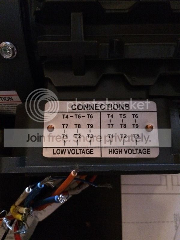
3. The other end of that cord (with the Green, Yellow, Brown, Red wires) needs to go to the motor. There are 9 numbered wires T1-T9, I know they get connected per the diagram on the motor. So for example T1 & T7 get connected along with one of the wires on the connecting cord using a wire nut. But what color wire gets connected to that combination of T#'s? The diagram says T1&T7 T2&T8 T3&T9 and then T4,5,6 go with eachother. But for the combination of two T wires, which color from the cord gets added?
4. In the last pic you'll see a tag attached to two smaller diameter wires. It says these leads terminate three 140C normally closed thermostats. My question is what do I do with those wires? The ends are bare exposed wire, do I just leave them like that?
Guys, seriously thank you so much for anyone willing to help me out with this long post, and for your patience. I realize this is probably first grade stuff for most, thank you for the help!")
Casey
IMG[ ]IMG
]IMG
IMG[ ]IMG
]IMG
IMG[ ]IMG
]IMG
Question 1 kind people (also I really need layman terms please, sorry I am a total newbie with this)
I connected the power cord (the one with prongs on the end) with 3 wires (Green, Black, White) inside the VFD. I connected Black to L1, White to L2, and Green to the green screw. Is this correct?
2. I have another cord (2ft long) to connect the VFD to the motor. It has 4 wires on each end. They are Green, Yellow, Brown, and Red. These I'm assuming need to be connected to the 3 screws shown in below picture (Green I know should go to green ground screw). The screws are labeled U V W, which color wire goes to which letter screw??
IMG[
 ]IMG
]IMG3. The other end of that cord (with the Green, Yellow, Brown, Red wires) needs to go to the motor. There are 9 numbered wires T1-T9, I know they get connected per the diagram on the motor. So for example T1 & T7 get connected along with one of the wires on the connecting cord using a wire nut. But what color wire gets connected to that combination of T#'s? The diagram says T1&T7 T2&T8 T3&T9 and then T4,5,6 go with eachother. But for the combination of two T wires, which color from the cord gets added?
4. In the last pic you'll see a tag attached to two smaller diameter wires. It says these leads terminate three 140C normally closed thermostats. My question is what do I do with those wires? The ends are bare exposed wire, do I just leave them like that?
Guys, seriously thank you so much for anyone willing to help me out with this long post, and for your patience. I realize this is probably first grade stuff for most, thank you for the help!
Casey
IMG[
 ]IMG
]IMGIMG[
 ]IMG
]IMGIMG[
 ]IMG
]IMG