- Joined
- Sep 14, 2010
- Messages
- 288
If this has been posted before I do apologize but I have not been able to find it. We have a sticky for the PID setup for a gas forge but not for an electric oven so with the help of Jawilder. Jason drew the schematic for me and was a huge help in this project as I based it off on he had build using an old tool box. I too was going to use a tool box but my dad snag it when he saw I was going to cut up a new one so I condensed it and its probably more efficient this way as the fans can draft the air across the heatsinks better. So in the end we were both happy!
I purchased the sugar creek big knife oven 230v without the controller and used the links provided by Stacy to purchase the Auber ramp/soak PID as well as the 2 SSR's, 2 heatsinks with heatsink paste and some misc switches and plugs. The main reasons I purchased the Auber PID with ramp/soak are others here have and know how to operate it and at some point in my journey ramp/soak will be more useful to me so might as well get it now.
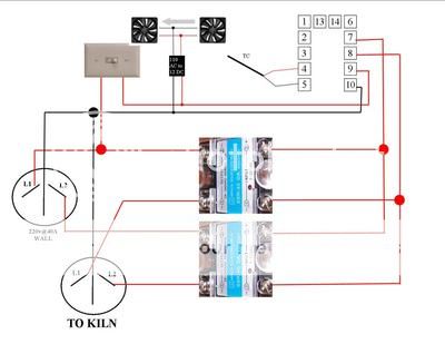
Here is the schematic Jason drew up which includes two fans that he wired in and sent me, Thanks bro! This is for the Auber SLY-2352P If you have a different PID the back of the inputs will probably not be the same but similar so be sure you hook up your PID according to the manufacturer specs.
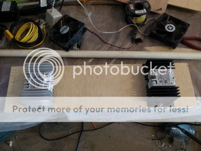
I stared by ripping a piece of plywood 5 1/8 wide and 20"s long which is 1/16 wider on each side of the heatsinks. Use the heatsink paste on the bottom of the SSR's and glue them to the heatsink. Then just screw them down.
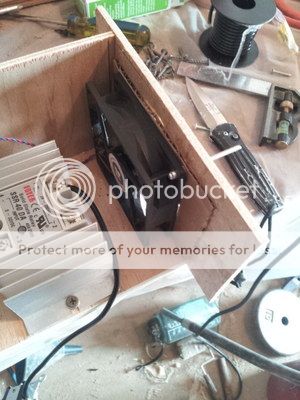
I began wiring up the inputs and outputs according to the schematic Jason made. If you are wondering why all the wire is the same color its because 1 I am colorblind and 2 its cheaper than buying another roll To cut down on splicing all the wires I cut them long and ran them in series using 12g wire through out with connectors. Just trace out each line and double check your work when done. In the pic below I went ahead and wired in an on/off switch that will prevent any power to the coils or the fans till I am ready for it.

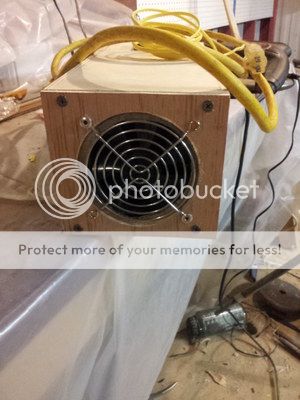
The fans I believe came from a dead computer and are DC so they need an AC to DC converter. You can buy AC fans like these that run on 110v and skip the converter all together but free is better! When you install the fans you want to make certain they are blowing in the same direction so they can draft the heat from the heatsinks out of the enclosure and keep things running cool. The grate is over the intake and I used a hole saw to cut out the opening. Once happy with the fit I pop rivet the fans in place. I wired in the pig tail for the fans to the 110v switch and ground. After that I checked the wiring and schematic twice more.
All that is left is to add the power cord and the thermocouple wire. I opted to use the thermocouple that came with the oven instead of drilling an second hole for another thermocouple as I dont want to mess the new oven up but later I may run another redundant probe. Make certain the cable you chose can handle the voltage you will be using. 10g cable is what I had on a broken extension cord so its what I used. Once everything is wired in check the wiring again then close up the box. After I test the controller I will added some metal trim and face plates but till we know it works we will hold off.


All that is left is to add the correct plug onto the power cable and plug it all in for a test run which will wait till tomorrow. I will also add a 110v outlet so I can use the contorller to run my toaster oven too. I will add the type K probe to the toaster oven and plug the oven in to the 110v outlet and we are good to go!
As to how to program and run the controller I dont yet know so more learning to do!
I hope you have enjoyed the build and thank you for reading this far. With Jason's help it was an easy build and I hope it helps others should they decide to add a PID to their HT oven or temper oven.
I purchased the sugar creek big knife oven 230v without the controller and used the links provided by Stacy to purchase the Auber ramp/soak PID as well as the 2 SSR's, 2 heatsinks with heatsink paste and some misc switches and plugs. The main reasons I purchased the Auber PID with ramp/soak are others here have and know how to operate it and at some point in my journey ramp/soak will be more useful to me so might as well get it now.
Here is the schematic Jason drew up which includes two fans that he wired in and sent me, Thanks bro! This is for the Auber SLY-2352P If you have a different PID the back of the inputs will probably not be the same but similar so be sure you hook up your PID according to the manufacturer specs.
I stared by ripping a piece of plywood 5 1/8 wide and 20"s long which is 1/16 wider on each side of the heatsinks. Use the heatsink paste on the bottom of the SSR's and glue them to the heatsink. Then just screw them down.
I began wiring up the inputs and outputs according to the schematic Jason made. If you are wondering why all the wire is the same color its because 1 I am colorblind and 2 its cheaper than buying another roll
To cut down on splicing all the wires I cut them long and ran them in series using 12g wire through out with connectors. Just trace out each line and double check your work when done. In the pic below I went ahead and wired in an on/off switch that will prevent any power to the coils or the fans till I am ready for it.
The fans I believe came from a dead computer and are DC so they need an AC to DC converter. You can buy AC fans like these that run on 110v and skip the converter all together but free is better! When you install the fans you want to make certain they are blowing in the same direction so they can draft the heat from the heatsinks out of the enclosure and keep things running cool. The grate is over the intake and I used a hole saw to cut out the opening. Once happy with the fit I pop rivet the fans in place. I wired in the pig tail for the fans to the 110v switch and ground. After that I checked the wiring and schematic twice more.
All that is left is to add the power cord and the thermocouple wire. I opted to use the thermocouple that came with the oven instead of drilling an second hole for another thermocouple as I dont want to mess the new oven up but later I may run another redundant probe. Make certain the cable you chose can handle the voltage you will be using. 10g cable is what I had on a broken extension cord so its what I used. Once everything is wired in check the wiring again then close up the box. After I test the controller I will added some metal trim and face plates but till we know it works we will hold off.
All that is left is to add the correct plug onto the power cable and plug it all in for a test run which will wait till tomorrow. I will also add a 110v outlet so I can use the contorller to run my toaster oven too. I will add the type K probe to the toaster oven and plug the oven in to the 110v outlet and we are good to go!
As to how to program and run the controller I dont yet know so more learning to do!
I hope you have enjoyed the build and thank you for reading this far. With Jason's help it was an easy build and I hope it helps others should they decide to add a PID to their HT oven or temper oven.
Last edited: