-
The BladeForums.com 2024 Traditional Knife is available! Price is $250 ea (shipped within CONUS).
Order here: https://www.bladeforums.com/help/2024-traditional/
You are using an out of date browser. It may not display this or other websites correctly.
You should upgrade or use an alternative browser.
You should upgrade or use an alternative browser.
thermocouple and multi meter
- Thread starter cjd1980
- Start date
Stacy E. Apelt - Bladesmith
ilmarinen - MODERATOR
Moderator
Knifemaker / Craftsman / Service Provider
- Joined
- Aug 20, 2004
- Messages
- 38,479
If you run a venturi forge with a PID connected to a solenoid, it will go on and off. There will be a WOOF every time it re-ignites. The hot forge will provide the ignition, but it can be a bit disconcerting. A venturi needs a good bit of pressure to draw the air (venturi principle) and having a two stage venturi is not really practical. J
The practical solution is to just make the burner arm a blown burner. It is simpler than making a venturi, and completely adjustable. You can then set it up as you wish. It is very hard to run a venturi at lower forge temperatures. Even keeping it at 1500F can be a problem without back flash. A blown burner can run at virtually any temperature desired.
Stacy
")
 Where's that "in-depth, detailed" post that you were supposed to make?
Stacy E. Apelt - Bladesmith
ilmarinen - MODERATOR
Moderator
Knifemaker / Craftsman / Service Provider
- Joined
- Aug 20, 2004
- Messages
- 38,479
Things have been crazy for the past several days. I sing in the choir, and this week there are services Thursday, Friday, and Sunday, with a full cantata next week. The music director was injured in a car accident Tuesday ( broken shoulder and minor neck injuries), so I stepped in to cover the music direction. We obtained a fill in pianist/organist, and while she is a fine musician, she is old and can't play faster more modern pieces (like what we had been practicing for this week and the cantata next week). I re-did the music for the Maundy Thursday and Good Friday services to be simple slower pieces, and have written an arrangement of "Christ Arose" for Easter Sunday, to replace the much faster "He's Not Here", we had planned. At this point we are just postponing the cantata. It is pretty lively, so maybe we will do it as a Pentecost cantata ( that would be a first).
OK, enough whining:
I recommend you do some searches and reading on the many threads on this subject. It may take some time, but there have been several great build threads on this design. Until you get the principle in your head, you will just be riding the trolley back and forth, but never getting anywhere. Once you see the light bulb go on, it is...."Oh, is that all it is!!!"
Here are a few starter searches. Read all the posts, there are some tidbits tucked in as well as great photos and schematics:
On a single stage build for a venturi forge:
http://andersonknives.ca/Digitally Controlled Forge.html
On the two stage blown controller:
http://www.bladeforums.com/forums/showthread.php?t=523845
http://www.bladeforums.com/forums/showthread.php?t=600318&highlight=PID
http://www.bladeforums.com/forums/showthread.php?t=599953&highlight=forge
To recap the info you will get from these threads:
A two stage burner control has a by-pass needle valve that is set to run the forge at a lower than target temperature. It has a fan control that balances the flame at that lower setting, also. The HI control section has a solenoid valve to allow the gas to flow through a second path to reach a higher temperature.This has a fan control also. The PID switches the burner from the LO to the HI as the thermocouple reading tells it to. Temperature regulation is very tight, with +/- 1 degree possible. The forge atmosphere is always balanced,too.
I will try and get the final schematic sketch for the ultimate controller finished soon. JT was doing a draw program cleanup of the basic burner control. I'll rattle him and see how it is coming.
Stacy
- Joined
- Jun 21, 1999
- Messages
- 752
Stacy I just want to thank you for all the sharing. I got a blast furnace at an auction a few months ago and have been planning on putting a PID on it (currently just has a dial). When I actually get the time and money to buy al the parts, I'll have all the info here. Thanks! Now you've got me considering making a portable unit and using it on my blown forge as well.
Again, thanks for sharing your knowledge!
Ed
Again, thanks for sharing your knowledge!
Ed
Stacy E. Apelt - Bladesmith
ilmarinen - MODERATOR
Moderator
Knifemaker / Craftsman / Service Provider
- Joined
- Aug 20, 2004
- Messages
- 38,479
Sit tight folks, I just got back from church. I typed a good bit last night, and will try and post part of the info later today. Since JT is laid up, I'll just redraw the plans by hand for the time being.
Going to prepare Fillet Mignon for dinner.
Stacy
Going to prepare Fillet Mignon for dinner.
Stacy
- Joined
- Oct 21, 2006
- Messages
- 1,652
mmm, you always eat well it sounds like =D (at least every meal you post)
Thank you very much for the info that you've provided on a PID controlled burner, that's on my list of things to do this summer when i find the time, and you, as usual, have been an invaluable resource to the community.
Myself, i'm a horrible cook, so i'm ordering bonless spare ribs and fried rice for supper, and pouring myself a glass of my Laphroaig cask strength when supper time rolls around =)
Stacy E. Apelt - Bladesmith
ilmarinen - MODERATOR
Moderator
Knifemaker / Craftsman / Service Provider
- Joined
- Aug 20, 2004
- Messages
- 38,479
Since it is a special holiday, I'll sip some of the 100 year old bottle of Scotch.
I will post some of the info now, and put up the drawings as soon as I get them finalized.These are excerpts from emails and directions to people:
Running a toaster oven from a PID
I used to write field change manuals for the government. They must be able to be read by a monkey (one that can read ,of course), and have the modification of an sophisticated electronic device done with the minimum of tools and knowledge, away from an fully outfitted electronics shop.
In an effort to help those who are challenged by trying to connect a PID and its associated circuitry to a device, I will give the procedure and setup to run a toaster oven as a tempering oven. The same hookup can run a variety of things (solenoid valve on a forge, salt pot, BBQ smoker, kiln, etc.), with the appropriate thermocouple and SSR. If you only want it to read temperature, you just use the thermocouple as a thermometer, and plug in no load device.
Some components can be found in thrift stores, other from electronics suppliers, and most everything can be purchased on Ebay. Search Ebay for PID, Thermocouple K, SSR, Thermocouple plug connector, 120V cooling fan.
The Oven:
Any toaster oven will do fine. It only needs to be able to set the oven on HIGH or have a temperature setting knob. You are going to permanently set it on high or the highest setting anyway. It needs nothing modified beyond a small hole drilled to allow the thermocouple to stick inside. Some folks wrap a blanket of insulation around the oven to get a little more efficiency. That probably isn‘t a bad idea, but use a proper insulation. A piece of insuwool is NOT a good idea. You want a jacket insulation, which controls the loose fibers, like a water heater wrap from the hardware or plumbing shop. Wrap the entire toaster, including the back and tape the jacket with duct tape. Leave a flap to drop over the front door. This will greatly help the oven regulate temperature, and hold a somewhat higher temperature.
The PID:
Most PID controllers are pretty much the same. You want 120VAC input and the ability to take type K thermocouples. Nearly every one I have seen does that.
Here is a basic unit from a supplier that many smiths buy from:
http://cgi.ebay.com/UNIVERSAL-PID-T...50926QQcmdZViewItemQQ_trksidZp1742.m153.l1262
The Thermocouple:
The Thermocouple that they often give you with those controllers is pretty useless for most of our purposes, so you will need a new one. The temperature range needs to match the desired use. If it is going into an electric toaster oven, it just needs to be a type K that is long enough ( 4-5”") and rated at 1000F. (There is a + and - wire, BTW, make sure you hook them up right or the display will read minus.) Some come with wires and some have just bare ends . You can use a thermocouple mounting block, or connect the thermocouple wire directly to the bare ends. You need to use specific thermocouple wire for connecting the probe to the PID.A good idea is to use a plug in probe and put a corresponding socket on the thermocouple wire. That way ,changing probes or moving the controller to a different device can be easily done.
and rated at 1000F. (There is a + and - wire, BTW, make sure you hook them up right or the display will read minus.) Some come with wires and some have just bare ends . You can use a thermocouple mounting block, or connect the thermocouple wire directly to the bare ends. You need to use specific thermocouple wire for connecting the probe to the PID.A good idea is to use a plug in probe and put a corresponding socket on the thermocouple wire. That way ,changing probes or moving the controller to a different device can be easily done.
Here is a basic 5” medium temperature thermocouple:
http://cgi.ebay.com/Thermocouple-2-...14&_trkparms=72:1205|66:2|65:12|39:1|240:1318
A higher temperature and more robust probe is like this:
http://cgi.ebay.com/Thermocouple-2-...14&_trkparms=72:1205|66:2|65:12|39:1|240:1318
Plug in Probe:
http://cgi.ebay.com/Thermocouple-2-...14&_trkparms=72:1205|66:2|65:12|39:1|240:1318
The SSR:
The SSR is actuated by the output voltage from the SSR control circuit on the PID. Most PID output voltage is 8VDC, some are 12VDC.
The SSR units usually take 3-48VDC input, and control 48-480VAC .The amperage needs to be enough to run the device being controller, plus a bit. Most folks just use a 25Amp SSR. You will need a heat sink on the SSR to keep it from burning out ( they only will take 3-5 amps otherwise). A small fan, like from a computer , should be used to cool the heat sink. Here is a basic SSR and heat sink:
http://cgi.ebay.com/Solid-State-Rel...36328QQcmdZViewItemQQ_trksidZp1742.m153.l1262
120VAC Fan:
http://cgi.ebay.com/COOLING-FAN-120...14&_trkparms=72:1205|66:2|65:12|39:1|240:1318
To hook all this up:
Enclosure:
Select or make a suitable cabinet for the controller. While you can mount it all on a board, open circuitry with 120VAC is a bad idea. A piece of plywood , or Plexiglas, with a plastic bread storage container on the back (to cover the wires) will work if you don’t want anything fancier.
On the PID -
Cut the cabinet/mounting board to fit the PID. It inserts into the hole and snaps in. Yours may have come with a case or mounting plate of some sort, so mount it as needed.
Connect the thermocouple to the + and - contact screws. Observe the polarity of the probe.
Connect two 16 gauge wires, about 12” long, to the AC POWER screws. A piece of lamp cord does fine.
Connect two 18gauge SSR control wires to the SSR screws ( about a foot long). They are + and -.Use red and black wires. There may be some jumper wires or clips to connect as the directions will tell you.
On the SSR:
Mount the SSR on the heat sink as described in its instructions ( it may recommend using heat sink compound, which is a good idea). Make sure the cabinet or enclosure has sufficient air flow to aid cooling.
Connect the red/black wires from the PID to the corresponding CONTROL contacts on the SSR.
Connect the black wire on the 3’ piece of extension cord to one of the LOAD contacts on the SSR. Connect a 14 gauge, 12” long black AC wire to the other LOAD contact (see POWER below).
Mount the SSR over the fan ,so the air blows through the fins and cools the SSR.
The fan connects to the 120VAC . (see POWER below)
POWER:
You will need a 9 foot , 15 amp rated extension cord. Cut it off about 3 feet from the female (socket) end. There will be several things connected to these cords, so set up a power buss (multi connection strips) is simplest and safest, but wire nuts will work. Connection wires should be white and black and of 14 gauge . Securely fasten the male and female power cord pieces to the case with cable clamps of some fashion.
On the panel, install a SPST power switch and a 15 amp fuse. Connect the black wire from the male power cord (the 6 foot long piece with a plug) to the switch and the switch to the fuse.
There is a common wire (white) and a load wire(black) and a ground wire (green).
Install a black AC wire from the fuse to the load power buss. At this buss the connections are made to:
The load contact on the SSR, The PID, and The fan.
The white wire from the power cord goes to a common buss at which the connections are made to :
The white wire on the Female power cord end (3 foot piece with a socket), The PID, The fan.
The green wires form the two cords are connected together.
The toaster oven ( or controlled device) plugs into the female cord. The male cord will plug into the wall socket.
Insert the thermocouple into the oven chamber. Affix as needed. If the thermocouple is installed just below the rack/grate/shelf, it can be affixed with a twist of bare wire. That way it reads the temperature close to the blade being tempered.
For a really accurate reading, drill a 3” to 4” deep hole in the end of a ½-¾” thick plate of aluminum or steel. The hole should just accommodate the probe. The piece of metal should be the same size as the rack in the oven .This plate will replace the rack. The probe will insert into the hole. The blade will rest on the plate. Drill the probe hole in the side of the oven first. Then mark the plate and drill the hole in it to assure alignment .
You only want the probe in the oven, not its wires. Use a longer probe if needed for larger ovens. The tip of the probe is what reads the temperature, so as long as it is several inches in the oven chamber, it will be fine.
The operation of the PID is simple and the instructions give the setup and programming. A good supplier will offer support help. The basic operation is to set the desired temperature (set point or set value) and turn the control program on. The toaster oven is permanently set at its highest setting, and will be turned on and off by the controller and the power switch. The controller will allow the power to flow to the oven until the temperature is reached. Then it will cycle on and off to maintain that setting. The PID will auto tune itself to learn how to hold the temperature evenly. There are a lot of strange words ,like hysterisis, in the instructions, but once set up it is pretty simple to operate.
Hope this helps clear some of the mystery.
Stacy
I will post some of the info now, and put up the drawings as soon as I get them finalized.These are excerpts from emails and directions to people:
Running a toaster oven from a PID
I used to write field change manuals for the government. They must be able to be read by a monkey (one that can read ,of course), and have the modification of an sophisticated electronic device done with the minimum of tools and knowledge, away from an fully outfitted electronics shop.
In an effort to help those who are challenged by trying to connect a PID and its associated circuitry to a device, I will give the procedure and setup to run a toaster oven as a tempering oven. The same hookup can run a variety of things (solenoid valve on a forge, salt pot, BBQ smoker, kiln, etc.), with the appropriate thermocouple and SSR. If you only want it to read temperature, you just use the thermocouple as a thermometer, and plug in no load device.
Some components can be found in thrift stores, other from electronics suppliers, and most everything can be purchased on Ebay. Search Ebay for PID, Thermocouple K, SSR, Thermocouple plug connector, 120V cooling fan.
The Oven:
Any toaster oven will do fine. It only needs to be able to set the oven on HIGH or have a temperature setting knob. You are going to permanently set it on high or the highest setting anyway. It needs nothing modified beyond a small hole drilled to allow the thermocouple to stick inside. Some folks wrap a blanket of insulation around the oven to get a little more efficiency. That probably isn‘t a bad idea, but use a proper insulation. A piece of insuwool is NOT a good idea. You want a jacket insulation, which controls the loose fibers, like a water heater wrap from the hardware or plumbing shop. Wrap the entire toaster, including the back and tape the jacket with duct tape. Leave a flap to drop over the front door. This will greatly help the oven regulate temperature, and hold a somewhat higher temperature.
The PID:
Most PID controllers are pretty much the same. You want 120VAC input and the ability to take type K thermocouples. Nearly every one I have seen does that.
Here is a basic unit from a supplier that many smiths buy from:
http://cgi.ebay.com/UNIVERSAL-PID-T...50926QQcmdZViewItemQQ_trksidZp1742.m153.l1262
The Thermocouple:
The Thermocouple that they often give you with those controllers is pretty useless for most of our purposes, so you will need a new one. The temperature range needs to match the desired use. If it is going into an electric toaster oven, it just needs to be a type K that is long enough ( 4-5”
and rated at 1000F. (There is a + and - wire, BTW, make sure you hook them up right or the display will read minus.) Some come with wires and some have just bare ends . You can use a thermocouple mounting block, or connect the thermocouple wire directly to the bare ends. You need to use specific thermocouple wire for connecting the probe to the PID.A good idea is to use a plug in probe and put a corresponding socket on the thermocouple wire. That way ,changing probes or moving the controller to a different device can be easily done.Here is a basic 5” medium temperature thermocouple:
http://cgi.ebay.com/Thermocouple-2-...14&_trkparms=72:1205|66:2|65:12|39:1|240:1318
A higher temperature and more robust probe is like this:
http://cgi.ebay.com/Thermocouple-2-...14&_trkparms=72:1205|66:2|65:12|39:1|240:1318
Plug in Probe:
http://cgi.ebay.com/Thermocouple-2-...14&_trkparms=72:1205|66:2|65:12|39:1|240:1318
The SSR:
The SSR is actuated by the output voltage from the SSR control circuit on the PID. Most PID output voltage is 8VDC, some are 12VDC.
The SSR units usually take 3-48VDC input, and control 48-480VAC .The amperage needs to be enough to run the device being controller, plus a bit. Most folks just use a 25Amp SSR. You will need a heat sink on the SSR to keep it from burning out ( they only will take 3-5 amps otherwise). A small fan, like from a computer , should be used to cool the heat sink. Here is a basic SSR and heat sink:
http://cgi.ebay.com/Solid-State-Rel...36328QQcmdZViewItemQQ_trksidZp1742.m153.l1262
120VAC Fan:
http://cgi.ebay.com/COOLING-FAN-120...14&_trkparms=72:1205|66:2|65:12|39:1|240:1318
To hook all this up:
Enclosure:
Select or make a suitable cabinet for the controller. While you can mount it all on a board, open circuitry with 120VAC is a bad idea. A piece of plywood , or Plexiglas, with a plastic bread storage container on the back (to cover the wires) will work if you don’t want anything fancier.
On the PID -
Cut the cabinet/mounting board to fit the PID. It inserts into the hole and snaps in. Yours may have come with a case or mounting plate of some sort, so mount it as needed.
Connect the thermocouple to the + and - contact screws. Observe the polarity of the probe.
Connect two 16 gauge wires, about 12” long, to the AC POWER screws. A piece of lamp cord does fine.
Connect two 18gauge SSR control wires to the SSR screws ( about a foot long). They are + and -.Use red and black wires. There may be some jumper wires or clips to connect as the directions will tell you.
On the SSR:
Mount the SSR on the heat sink as described in its instructions ( it may recommend using heat sink compound, which is a good idea). Make sure the cabinet or enclosure has sufficient air flow to aid cooling.
Connect the red/black wires from the PID to the corresponding CONTROL contacts on the SSR.
Connect the black wire on the 3’ piece of extension cord to one of the LOAD contacts on the SSR. Connect a 14 gauge, 12” long black AC wire to the other LOAD contact (see POWER below).
Mount the SSR over the fan ,so the air blows through the fins and cools the SSR.
The fan connects to the 120VAC . (see POWER below)
POWER:
You will need a 9 foot , 15 amp rated extension cord. Cut it off about 3 feet from the female (socket) end. There will be several things connected to these cords, so set up a power buss (multi connection strips) is simplest and safest, but wire nuts will work. Connection wires should be white and black and of 14 gauge . Securely fasten the male and female power cord pieces to the case with cable clamps of some fashion.
On the panel, install a SPST power switch and a 15 amp fuse. Connect the black wire from the male power cord (the 6 foot long piece with a plug) to the switch and the switch to the fuse.
There is a common wire (white) and a load wire(black) and a ground wire (green).
Install a black AC wire from the fuse to the load power buss. At this buss the connections are made to:
The load contact on the SSR, The PID, and The fan.
The white wire from the power cord goes to a common buss at which the connections are made to :
The white wire on the Female power cord end (3 foot piece with a socket), The PID, The fan.
The green wires form the two cords are connected together.
The toaster oven ( or controlled device) plugs into the female cord. The male cord will plug into the wall socket.
Insert the thermocouple into the oven chamber. Affix as needed. If the thermocouple is installed just below the rack/grate/shelf, it can be affixed with a twist of bare wire. That way it reads the temperature close to the blade being tempered.
For a really accurate reading, drill a 3” to 4” deep hole in the end of a ½-¾” thick plate of aluminum or steel. The hole should just accommodate the probe. The piece of metal should be the same size as the rack in the oven .This plate will replace the rack. The probe will insert into the hole. The blade will rest on the plate. Drill the probe hole in the side of the oven first. Then mark the plate and drill the hole in it to assure alignment .
You only want the probe in the oven, not its wires. Use a longer probe if needed for larger ovens. The tip of the probe is what reads the temperature, so as long as it is several inches in the oven chamber, it will be fine.
The operation of the PID is simple and the instructions give the setup and programming. A good supplier will offer support help. The basic operation is to set the desired temperature (set point or set value) and turn the control program on. The toaster oven is permanently set at its highest setting, and will be turned on and off by the controller and the power switch. The controller will allow the power to flow to the oven until the temperature is reached. Then it will cycle on and off to maintain that setting. The PID will auto tune itself to learn how to hold the temperature evenly. There are a lot of strange words ,like hysterisis, in the instructions, but once set up it is pretty simple to operate.
Hope this helps clear some of the mystery.
Stacy
Stacy E. Apelt - Bladesmith
ilmarinen - MODERATOR
Moderator
Knifemaker / Craftsman / Service Provider
- Joined
- Aug 20, 2004
- Messages
- 38,479
The two stage system works by cycling the burner from high to low to maintain a set point. This is much more accurate than cycling from on to off.
The procedure to pre-set the burner is this:
Turn off the MAIN gas valve.
Turn off both MAIN and CONTROL power switches.
Set the LOW fan control halfway clockwise.
Open the LOW gas needle valve halfway.
Turn the HIGH fan control fully counter clockwise (off).
Turn the HIGH gas needle valve off.
Turn on the gas at the tank, adjusting the regulator to about three pounds pressure. Increase the pressure as needed during the setting procedures to attain the desired temperatures. Generally the regulator should finally be set about one pound higher than the necessary pressure needed to hold the HIGH setting.
Turn on the MAIN power switch (the one to the PID).
Set the PID at a setting 300 degrees above the target temperature.
Turn on the PID function ( but leave the CONTROL switch off).
Place a burning piece of paper in the forge, and open the main gas valve.
Adjust the LOW fan and LOW gas for a steady neutral burn and allow the forge to heat up. Let heat for five or ten minutes.
When fully heated up, adjust the air/gas to get the temperature to a steady reading about 1200F . Allow forge to soak to this temperature for five minutes, adjusting the air/gas to a neutral flame.
The forge should be fairly stable at this 1200F point . This is the minimum LOW setting.
Turn on the CONTROL switch (which energizes the SSR).
Turn the HIGH fan halfway clockwise.
Turn the HIGH gas up to get a balanced flame.
Continue to adjust the gas/air slowly until the forge reaches a point about 200 degrees above the target. Allow to run for a couple minutes to get stable. Adjust to a neutral flame.
When all is running right at a temperature about 200 degrees above the target, it is now set for the max HIGH point.
Re-set the PID to the target temperature. The controller should turn the solenoid (high) off and allow the chamber to fall to the target. It will then turn on and cycle on and off to keep the chamber at the target.
At this point the controller is set. You can now set the PID to any value between the HIGH and the LOW.
You will not need to adjust the valves and fan controls again to operate the forge between these HIGH and LOW settings (unless you need to adjust the atmosphere, in which case you adjust the fan controls only) To change to values outside these high/low ranges, re-do the above steps to the new values.
To use the controller for Heat Treatment:
Turn the CONTROL switch off.
Turn the MAIN power switch on.
Set the target on the PID and turn the PID control function on.
Light the forge, allow to come up to the LOW setting of approx. 1200F. Let run for ten to fifteen minutes to fully soak the chamber.
Put in the blade in the chamber and allow to soak to the LOW setting (about one or two minutes).
Turn the CONTROL switch on.
The forge should rise to the target temperature and cycle on and off to maintain the target (usually plus or minus a couple degrees). If the temperature rises more than a few degrees above the target, and the solenoid is not de-energized , check that you have the PID in the on mode. Turn the CONTROL switch off if the unit is not working right, and check the PID settings.
Soak the blade for the desired time once the target temperature is reached and quench.
The CONTROL switch can be turned off to allow the forge to cool down and hold at approx 1200F until the next blade is ready to go in for HT.
The LOW setting is also good for sub-critical annealing.
When turning the forge off at the end of a burn, turn the MAIN gas valve off, let the fan run for a minute, then turn the MAIN power switch off. Close the valve at the tank.
Operation principle of the two stage controller:
When the PID energizes the SSR, the solenoid is turned on and the high fan control is energized. This switches the burner into the high mode. When the PID de-energizes the SSR (at the target setting) the burner runs in the low setting. With both extremes pre-adjusted to run at a neutral atmosphere, the burner flame never goes out, and the chamber atmosphere never changes.
This controller can be adjusted to run a properly built HT forge within +/- two degrees. In practicality, setting the PID to a range that allows for the burner to cycle on and off no more than two times a minute is a good practice. This prevents overworking the solenoid. For very specific HT parameters, it can be set to a closer range.
In the low mode the burner runs only on the low gas valve setting and the blower is receiving only the low fan controller setting.
In the high mode, the gas valves run parallel (delivering more gas), and the fan controllers run in a parallel resistance, delivering more power to the blower motor.
Stacy E. Apelt - Bladesmith
ilmarinen - MODERATOR
Moderator
Knifemaker / Craftsman / Service Provider
- Joined
- Aug 20, 2004
- Messages
- 38,479
This is a wrap up of the basic function and opperation.
PID Controlled Forge
To control a forge for forging or Heat Treatment, you connect the SSR from the previous PID article to a solenoid to turn the gas on and off, and to a fan control to control the amount of air being delivered to the burner ( if the forge has a blower).
A moment of discussion about running a forge.
In a venturi burner the air is drawn into the burner tube by the suction of the gas jet. This is called the Venturi principle. This requires an exact size orifice for the gas, higher pressures, and choking of the air port to control the air supply.
With a blown forge burner, the air is supplied by a fan, referred to as a blower. This air is mixed in the burner tube and enters the forge chamber as a combustible blend of fuel and oxidizer.
In either burner type, the amount of air determines the atmosphere of the forge chamber. If there is a balance of oxygen and fuel , all the fuel burns with no extra of either ingredient. This is referred to as a NEUTRAL atmosphere. If there is a shortage of oxygen ( less air flow) the fuel does not burn completely, leaving excess carbon in the exhaust gasses. This is called a REDUCING or CARBURIZING atmosphere. If there is excess oxygen, the fuel is completely burned and there is excess hot oxygen, it is called an OXIDIZING atmosphere. How can you tell which is which??? - By looking at the forge flame. First, allow the forge to heat up. A cold forge does not run with the efficiency of a fully heated chamber. Let it run for at least 5 minutes before fine tuning the air/fuel mix.
In a carburizing flame, the excess fuel will burn outside the forge chamber doors, with a yellowish flame. The excess carbon in this hot mix of gasses will eat up any free oxygen or other oxidizers, and reduce the scale and de-carburization ( decarb) of the blade. It can even add a minute amount of carbon to the steel’s surface. A slightly carburizing ( just above neutral) is the desired Heat Treatment flame.
In the neutral flame, the fuel and air burn efficiently in the forge chamber, and little or no “Dragon’s Breath” appears outside the forge doors. The chamber should be a good glow, with a blue flame with no yellow flames in it. This atmosphere will give the most efficient use of the fuel, with little or no scaling or de-carburization. This is the normal forging flame.
In a Oxidizing atmosphere, there is excess oxygen, from too much air, and the hot oxygen looks for some hot carbon (and other elements) to combine with. The carbon and iron in the steel react with the oxygen, producing iron oxide (scale) and loss of carbon ( decarb). This flame is hot, but to be avoided.
OK, now we know where we want to be, so lets get there.
In a venturi forge burner, the air is the problematic factor, and the fuel pressure must remain high enough to draw the air. As the fuel pressure drops, the air flow drops at a rate greater I proportion to the fuel drop. Thus as a venturi burner gets lower and lower, the venturi draws in less and less air, until the venturi collapses and the flame flashes back up the burner tube to the orifice. This is not a good thing, BTW. The point of collapse is hard to determine …..until you get there. The opening of the air choke as the fuel pressure is reduced is a mechanical process, and not easily adjusted from one temperature setting to another. So, with a venturi burner, the only practical way to control the forge temperature is to turn the burner on and off. By connecting the gas line to a solenoid valve, the burner can be switched on and off as the temperature reaches the target point (set point) and then drops below it. The problem with this is that during the off cycles the forge chamber gets filled with superheated air ( coming in through the doors) , and this makes a severely oxidizing atmosphere until the burner cycles back on again. If you run a controlled venturi burner, the WOOFFF every time it re-ignites and the change in atmosphere are things you have to live with. Not the end of the world, but less than the perfect world.
With a blown forge ,the air is delivered by a fan, which is often regulated by some sort of mechanical valve of choke. This will work fine for a fixed flame, unregulated forge, but will clearly be problematic if temperature control is added. The way around this is to made the blower control electrical, by way of a fan controller. This is simple a small rheostat or dimmer switch placed in the AC line to the fan motor. With a solenoid controlling the gas flow, and a rheostat controlling the air flow. The flame can be easily adjusted to balance the forge atmosphere, but the flame will cycle on and off. To add to the problem, the fan really should stay on to avoid re-ignition problems, so during the off cycles, the forge atmosphere is very oxidizing. The blower can be shut on and off along with the gas as the PID cycles on and off, but there are issues with when the air and fuel should mix in a hot tube. Let it suffice to say that this is not what you really want. So, are we no better off than with a venturi burner? At this point, yes….maybe worse. The sound of this type of setup is often called “Breathing“, as you hear the sound of the forge going on and off , making a panting sound.
Enter the two-stage burner control. There is a solenoid valve to control the gas, and a rheostat to control the fan, but the control is by-passed by a lower setting to thus cycle the flame from Hi to Low instead of on and off.
Let’s imaging you are alone on a football field and you want to go to the opposite end zone. You could run to the right 10 yard line, then to the left 20, back to the right 30...etc…until you got to the opposite goal posts. That would get you there, but a much more efficient and even way would be to run straight down the middle as closely as you can. That is what you want to do in controlling a forge - go straight done the middle not from max flame (above target) to off flame ( zero).
To do this you first create a non-regulated setup with a needle valve in the fuel line and a rheostat in the fan AC input. This is the standard non-controlled blown forge. You can set it to run as hot as the forge can go, or down to a barely visible flame that just barely warms the forge. Next, you add a parallel setup that has a PID controlling a gas solenoid valve ( with a second needle valve to adjust the gas), and a second rheostat to control the fan . These two circuits are adjusted so the LOW or OFF function will yield a forge temperature a little below the target, with a balanced atmosphere; and the HI or ON function will yield a temperature slightly above the target, again, with a balanced atmosphere. The cycling back and forth between the two may be barely noticeable. Temperature control can be regulated to within +/- one degree, but a practical setting is +/- 5 degrees.
The diagrams show how the valves and controls are arranged to do this very simply.
SETUP AND ADJUSTMENT
Once the two-stage control is built, it can be run without the PID function ( PID power on, but control switch off) by merely adjusting the LOW needle valve and LOW rheostat until the desired flame is burning in the forge. This is using the PID as a pyrometer only, the current forge temperature will be shown.
To set up the controller for regulated/controlled use:
Turn the PID on so it reads the temperature, but is not in the control mode ( control switch off). Adjust the LOW controls for a smooth and balanced flame and let the forge warm up for 5-10 minutes. Re-adjust the LOW settings until the temperature reads about 100 below the target temperature. For the purposes of this explanation, we are going to use a target of 1500F. Now, when the forge is holding around1400F ( it will slowly drift up, since it is unregulated, but around 1400F is fine), set the PID for 1700F and turn on the control switch. The solenoid should open, allowing the gas to flow through the second needle valve ( HI ). At the same time it will send AC voltage to the second fan control rheostat ( HI ). Open the HI needle valve and the HI fan control, adjusting both until the forge is holding around 1600F, with a balanced flame. Again, it is not critical that it is exactly at 1600F ,just around there. Now, re-set the PID for 1500F. The solenoid should close, and the flame should drop back to the LOW settings. As soon as the temperature drops below 1500F the flame will cycle back on, until it reaches 1500F and then will cycle off. This will continue ,holding the temperature at very close to the set point. With this adjustment, you can set the PID to any temperature from around 1450F to 1550F and the regulation will hold very close. Changing the set-up parameters for higher or lower temperatures will allow for any desired temperature to be controlled from a few hundred degrees to the max your burner is capable of. For practical purposes, it is not desired to try and control the temperature above 2000F or below 500F.
If you want a lower bottom setting do the set-up mat about 100F below that desired point.
For instance, if you wanted to pre-heat your O-1 at 1200F for 20 minutes, and then raise it to 1475F for a 10 minute soak, just use 1100F and 1700F as the setup points. After setting the forge to run LOW at 1100F, and HI at 1600F, you can program the PID to do the ramp (assuming your PID has a programmable capacity). If your PID isn’t programmable, do the setup for 1100F and 1600F and just change the PID setting from 1200F to 1475F after the pre-heat.
USE OF THE FORGE CONTROLLER FOR TEMPERING OVEN:
To switch the PID to run your tempering oven, as in the first article, just unplug the fan and solenoid, and plug in the oven cord. Unplug the thermocouple from the forge and plug in the thermocouple from the oven.
THE ULTIMATE CONTROLLER
The “Ultimate Controller” I have designed will control many devices, depending on how much you build into it. Even in its simplest form, you can switch from one device to another without a lot of difficulty. It can also be quickly set up to control a forge or oven that was not built for control .
Think of all the devices you would like to control, and all the things you would like to know the temperature of…..and build them in.
Some ideas are:
Controlled Forge
Tempering oven/toaster oven
HT kiln/oven
Checking quench tank temperature
Controlling two or more devices at the same time
Salt pot controller - gas or electric
Checking the kitchen oven temperature
Checking temperatures on exhaust pipes, turkey fryers, you name it
Accessory receptacle for work light, fan, radio,etc.
Ever wondered how hot the forge shell or burner arm is? Weld on some ¼-20 nuts ( or drill and tap holes ) and screw in some threaded stud thermocouples and you’ll know with the push of a button.
The advantages of building them all into one unit are :
Portability
Security ( put it away at night)
Convenience - Only one power cord, one place to check all controlled devices
Ease of changing devices - plugs instead of hard wiring
Ease of connection for gas lines - Quick connect fittings
Ease to convert any blown forge to control - just add quick connect fittings in the gas line and stick in a thermocouple. No rebuilding required, usually.
SUPER SIMPLE SALT POT QUENCH/TEMPERIN/BLUING TANK
A small pottery kiln can often be found for little or nothing. By cutting a hole in the top, installing a heavy walled tube, and connecting the kiln to a controller, this can make a great tank for marquenching, tempering, salt bluing, etc. The tube should be as heavily walled as you can get. 3’8 -½” is great, but at the relatively low temperatures it will be used at ¼” will do fine. The tube is filled with salts that become molten at the desired ranges. The salts can be purchased from suppliers such as Darren Ellis, Knife suppliers ( Bluing salts), and industrial suppliers. This type of conversion will not be a good choice for high temperature austinitizing salt baths, or for heating liquids.
Having several tubes, each filled with a specific salt, can allow the kiln to be used for several functions. Just change the tube.
As you may know, there are many problems to be dealt with in high temperature salt pots. Those problems do not exist for the most part on low temperature salt pots, like this conversion. However, the same safety rules apply.
Avoid any possibility of water getting dripped, sprayed, splashed into the tube.
450F will burn you bad. Molten salt will stick to skin. Wear gloves, protective gear, and think safety.
The kiln has electrical coils that are carrying high current AC. Be respectful of this and make sure there is no chance that the tank can contact the coils. Also, most salts are corrosive to the coils, so make good mechanical exclusion of drips and other external things at the hole in the top.
Have a cover for the tube while in use, preferably an insulated cover, and a tight fitting cover for storage (to exclude
Stacy E. Apelt - Bladesmith
ilmarinen - MODERATOR
Moderator
Knifemaker / Craftsman / Service Provider
- Joined
- Aug 20, 2004
- Messages
- 38,479
That shouild keep you guys busy for a couple hours.
Stacy
Stacy
- Joined
- Jul 27, 2003
- Messages
- 5,698
Now my head hurts.....
- Joined
- May 20, 2006
- Messages
- 21
Stacy, Your time and patience explaining all this is much appreciated. It will be copied and backed up.
Matt
Matt
Stacy E. Apelt - Bladesmith
ilmarinen - MODERATOR
Moderator
Knifemaker / Craftsman / Service Provider
- Joined
- Aug 20, 2004
- Messages
- 38,479
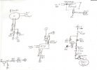
Here is a simple schematic sketch of the basic controller design. You can add to it as desired to spruce it up. Some ideas are:
Lights for Power ON,Low, High
A second pressure gauge after the needle valves (reads actual delivered pressure)
Any PID output functions you wish to use ( Alarm, relay, etc.)
A switch before the PID
This should be enough info for most of you to get the things together to make your forge controlled. As you can see. it is really only adding a duplicate set of regulation to the standard burner control ( needle valve and fan speed control). The second (parallel) control is activated by the PID, which also serves as the pyrometer.
I'll give you one tip that may not jump to your mind if you don't do a lot of gas plumbing. The gas loop will need a hose connection at the input and output of the solenoid/needle valve loop. This loop and the needle valves can be taken care of with welding hose fittings. Get a dual hose "Y" with needle valves (to run two hoses from a tank), and a regular (no valves) "Y" from the welding supplier. Use 1/4" hose bibbs (and short pieces of hose) or pipe fittings to hook the loop together (whichever is simpler for you).
Attachments
Stacy E. Apelt - Bladesmith
ilmarinen - MODERATOR
Moderator
Knifemaker / Craftsman / Service Provider
- Joined
- Aug 20, 2004
- Messages
- 38,479
The scan isn't super dark in the thumbnail, so I will give a written reading;
Starting at the propane tank, the items are:
Propane tank
Regulator (with gauge)
Main shutoff valve (ball valve)
10 foot hose (or whatever you need/have)
Quick Connect fittings (Darren Ellis)
Low needle valve
Solenoid - connects to "A" (AC common) and "C" (SSR power out)
High needle valve
6 foot hose to forge
Quick connect fitting
The AC plug :
Plug with ground
"A" - the common wire
Main fuse ( size depends on total power draw, in this case 5 amps is fine)
Main switch ( actually, it should be before the fuse, but doesn't matter)
"B" ( the hot terminal )
The BLOWER, coming from the bottom of the sketch:
"A" - the common wire
"B" - the hot wire
"C" - the controlled hot wire
Two fan speed controls
Blower motor
The PID:
"A" - common wire AC connection
"B" - hot wire AC connection
Fuse - PID protection fuse ( should be the max that the PID is rated for, probably 3 amps)
Thermocouple input +/-
SSR output
Switch in SSR + output ( could be DPST on both + and -) turns the control function off
The SSR:
+/- from the PID ( controll voltage, 3-28VDC usually ,from PID) turns SSR on and off
"B" - AC hot connection (AC input)
"C" - controlled hot AC to the solenoid and fan (AC output)
The FORGE:
Thermocouple
Air in
Gas in
Stacy
Last edited:
Stacy E. Apelt - Bladesmith
ilmarinen - MODERATOR
Moderator
Knifemaker / Craftsman / Service Provider
- Joined
- Aug 20, 2004
- Messages
- 38,479
Bumped back to the top so those who were in a chocolate induced coma can get a headache ,too.
Stacy
Stacy