When a problem comes along - you must WIP it!
Dave
15-yard penalty! Roughing the pun!

OK. I've had loads of fun with Sketchup. I should mention that I'm only willing to put a certain amount of time & money into this. After a certain point, I'd be better off just using the wheels & tensioner on a NWG or EERF project. That's why there's a $200 cap.
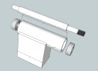
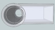
I. This is the Cadillac version - it requires some machine work and some welding. In case it's not obvious, the vertical arm from the Grizzly slides onto the protruding end of the round tubing. The bearings seat at each end and the shaft goes through the middle.
A) Basic BOM so far:
1. 3" x 5" x 0.25" rectangular tubing, 5.25" long if you're welding this, 6.25" if you're bolting the bore in.
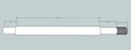
2. 1" x 12" shaft, turned and threaded to taste.
3. 2.5" OD, 1.5" ID DOM tubing 8" long.
4. 2 ball bearings. Bearings may end up being something more like 25mm ID and 47mm OD instead of 1" ID/2" OD. Metric bearings are a LOT easier to find.
B) My Sketchup skills aren't great.
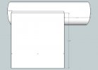
1. The drawings show the bore welded solid to the base, where I'll actually run about a 2-in-5 skip weld.
2. You could avoid welding at all if you drill & tap the DOM tube across the center at 1-11/16 (1.6875") and 4-3/16 (4.1875") from the pulley end, or the left if you're looking at Grinder2_3. Make the saddle in the rectangular tubing at the same height, raise the sides to 6-1/4" and bolt the bore in. I figure 3/8 fine thread should be plenty.
3. I snatched the bearing drawings as 3D Models off the web, so their OD, ID, and width are not to scale. Sue me.
")
C) It's also not all there:
1. I haven't decided whether to use 2 x 2 x 3/16 angle iron front & back to bolt the 3 x 5 tubing to the table or weld it to a flat plate.
2. It needs a mount point for a work rest. I'll probably just bolt the original work rest to the 3 x 5 for starters, but eventually I'd like to add a mount point for a MAP Arm style rest.
3. Obviously, I didn't get around to looking for a pulley. It goes on the unthreaded end.
II. The Honda Civic version. Minimal machining and no welding. No drawing yet.
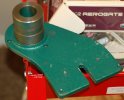
A) Make the rectangular tube 8" long, bolt a flange mount bearing on one narrow side and part 33C (See photo) from the grinder on the other.
B) Bore the end of 33C for your bearing and done. The same shaft and bearing dimensions as the Caddy version should work, with maybe some adjustment to length.
C) The stock workrest should bolt right up.
What do you guys think?
Doc