Would this grinder conversion work?

Joined
Feb 16, 2010
Messages
3,668
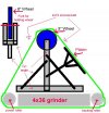
I've spent a lot of money on this small hobby so far. Not as much as some, but more than I expected to. I need to wait a year before I invest in a nicer grinder. However, I found a thread a while back about converting a 4x36 into a 2x72. Why couldn't I use the base, power roller, and tracking roller with a raised 8" wheel to extend the unit to drive a 2x72? I figure an "H" shaped base with a single post in the middle holding a fork at the top with the wheel installed there. Add a platen to the front and it should only take 4 bolts to install it onto the platen of the 4x36. Forgive my poor ability with paintshop, I did the best I could.

Perhaps there is a reason more haven't done this. Can someone chime in and tell me why this would or wouldn't work?
 

Attachments

  • grinder.jpg
    grinder.jpg
    36.1 KB · Views: 146
I think the basic consept is good, but I do see a few probs that will definately have to be addressed. The "tower" that mounts the 8" contact wheel seems a little flimsy by my guess. I think I might have to put that on triangular mounts instead of a post type. Once aligned and cross braced it will be alot more rigid.
Next, if you can engineer a way to rotate the whole thing to put the platen and then the contact wheel at a more comfortable, possibly safer position, you'd be near perfect to start with. Adding a work rest will present more issues, if you decide you want one.
Lastly, if you could manage a way to add variable speed, you not ever really need another.
 
The scale is off a little, but the triangular supports toward the rollers will be as high up as possible. I might even be able to add some angles to the sides, but I can only get about 2" from the center on each side. I had originally planned a double, large triangular base with cross supports. This design seemed to be simpler, since the main force will be vertical with little force back or front on the wheel. Most force will be on the platen, and that is pretty well braced. I could actually support the platen more than is shown on the diagram.

I forgot to mention that it is being built out of 304L stainless 1"x1"x1/8" angle. The contact wheel? I hadn't planned on using it as such, just a large roller for the belt.

Should the belt move up or down on the vertical platen? If down, I would move the platen to the other side, by the power roller.
 
OK thats a little difficult to explain. I'll assume the tracking adj roller is also the tension adj.
If that is the case you really need the belt going up the platen. The idea is that any drag you put on the belt (grinding) will pull the belt tighter on the drive wheel. All slack in the belt should go to the tennsion wheel before it gets to work surface.
 
The contact wheel? I hadn't planned on using it as such, just a large roller for the belt.

I wondered about that when I saw the design. I was going to suggest you put the contact wheel in a position where you wouldn't be forced to work blindly.

So if you weren't planning on using it as a contact wheel, then you don't want to do hollow grinds?

- Greg
 
It would be really nice to be able to change tooling around - sometimes you want a platen, sometimes a wheel, and sometimes a slack belt setup. Have you looked into some of the semi-do it yourself kits, like the Grinder in a box or the no weld grinder?

As these have been carefully designed by people who do grinding, with refinement of prototypes, these would probably better final product if they are within your budget.
 
Well, since no one has said it WON'T work, I will continue the planning. If I change the main support for the platen to a square tube instead of 1x1 angle, I could make it removable and adjustable. Also, after visiting a knife shop this morning and spending an hour there learning, I need to reverse the setup and work on the blade as the belt is moving toward the power roller. With a vertical platen, the belt should move down, not up.
 
Last edited:
The basic design looks sound but I would expect to have to use a much heavier tension spring right off the bat. A 4"x36" belt requires only a fraction of the tension you will need to make a 2"x72" belt track properly. Also, not having a crowned tracking wheel could make the tracking unstable, you might be able to address this by putting a narrow rib of tape around the center of the tracking wheel to form a crown.
The base/grinder frame might not be ridgid enough to properly support the extra weight of your attatchment in all positions. My old Craftsman was not terribly stable by itself, I do not think it would have held up well with the setup you have designed. You might have to do something to make the machine more stable.
I have had a Craftsman 4x36 and a HF 4x36 and the Craftsman had decent power. The HF unit had a better frame but had plastic wheels and a severely under-powered motor. So much so that I mounted a second motor to it and ran them in tandem for a while just to make it useable. It was essentially a waste of money. My point is that which unit you start with may make a big difference. Regardless what brand you use, I think your machine will have fairly limited performance capabilities.
Just some thoughts. I started to build a similar mod for my 6x48" but decided to get a Coote instead. Machine/tool building can be a very rewarding hobby in itself but I have learned to choose my battles carefully, they can become very time-consuming projects and often take considerable tweaking.
 
A heavier spring, ok. I can take it apart and see how the current spring works.
OK, there was a mention of 5-6 loops of electrical tape on the previous thread, but it didn't say why.
I did learn this morning that I don't press nearly as hard on the metal when grinding as other people do. I watched Dave make one half of a flat grind on a 5" blade in about the time that it takes me to get about 1/4 done on a 3" blade. So for now, I don't think the motor would be an issue. Although it probably will be in the future. Of course, by then I will probably get a better grinder, plus I could re-use this platen and roller.
 
The electrical tape build up will create a crown on the tracking wheel. This crown is what causes the belt to seek center when the wheel is square to the belt, and what causes it to walk to one side or the other when the tracking is adjusted off square. Kind of like how a bicycle turns when you lean to one side.
 
A slight change to the plans. . .I'm going with a 1.5" square tube from the base and a 1" square solid for the fork. Here's the question now, should I mount a bolt to hold it in place, or place a heavy duty spring inside the 1.5" square? A bolt would be much easier to adjust, but the spring would probably keep better pressure on the belt and eliminate the need for a separate tensioner.
 
Well, here is the first test build. The springs I am using have 40 lbs force at 1/2" travel. Now, I have to figure out how to remove the pressure so I can get the belt on. I need some way to drop the bottom of the spring by 1/2". Any thoughts?
 

Attachments

  • grinder 2.jpg
    grinder 2.jpg
    37.8 KB · Views: 28
Back
Top