- Joined
- Mar 8, 2008
- Messages
- 26,265
I post this in the full knowledge that it may rankle a sensitive few because some of my assertions on tool balance run counter to popular established lore. However romantic a notion that lore might be, both the theory and application of these concepts is based on pretty basic/simple physics and geometry that you can easily test yourself, and provide more concrete and pragmatic reasoning for the form of axes and other hand tools throughout history and across the globe. I consider this valuable information for anyone looking to gain a deeper understanding of the interplay of axe and handle design or looking to make their own handles. If you doubt my assertions you can easily confirm these principles with very minimal testing, and the beauty of it is that no familiarity with mathematics is required--just plumb lines and your own hands.
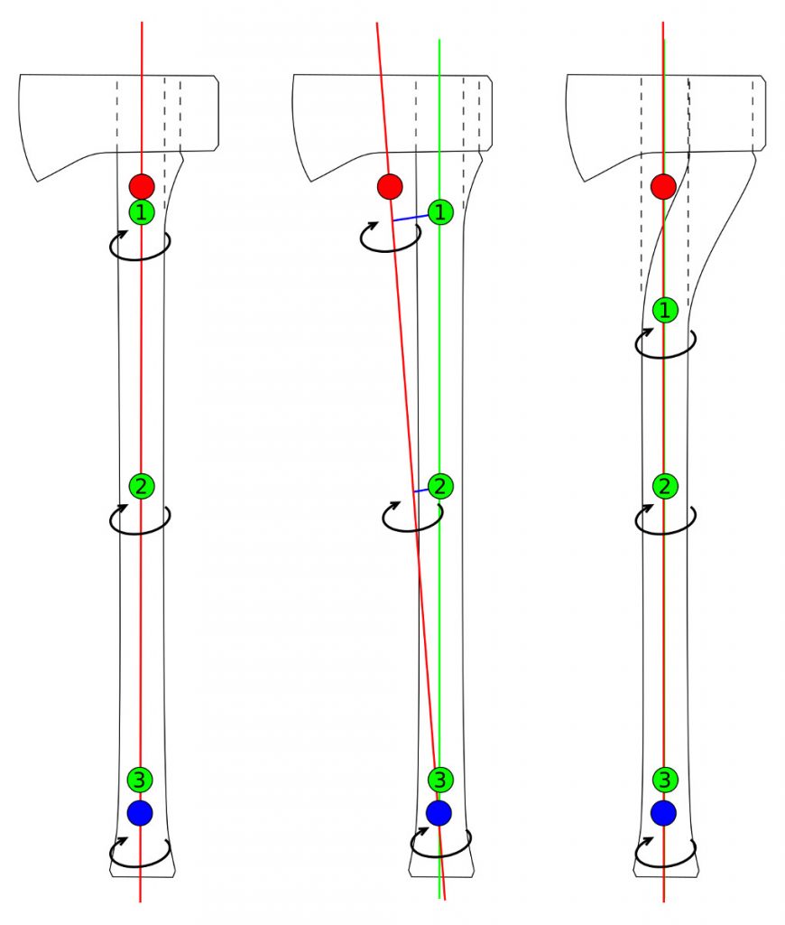
The above show the axle of the tool (red line) and corresponding lever arms (blue lines in center figure) of the tool when used with a sliding upper hand (numbered green dots) and fixed lower hand (blue dot.) As in previously posted diagrams, the red dot shows the center of gravity, and when the axle and handle diverge, the axis along which the hand is sliding is shown by a green line.
On the left you can see that the axe head is balanced by its large poll, and so a straight handle is an appropriate match, with no imbalances imparting torque on the hand in horizontal blows.
The middle axe has the same profile, but the eye has been shifted to the far rear, causing the center of gravity to shift forward in response. This now causes the handle to run off-axis and we can see the lever arms imparting torque on the axle at different points along its length as the upper hand position changes during a sliding stroke. As the hands converge we can see that the lever arm gets shorter and shorter until it becomes essentially insignificant. As such, the infamous “wobble” of a poll-less axe is mostly imparted at the beginning of the stroke, and–while not the ideal–if bearing this in mind it can be compensated for in technique by applying appropriate counter-torque at the start of the stroke and making the slide as early in the stroke as possible.
The third axe now shows the poll-less head with the handle corrected to bring the main length back along a unified axle. This axe will afford the bit size-to-head-weight advantages of a poll-less axe with mostly equal balance to the polled version. One will note that while the axe will now balance properly, the upper hand cannot go as high on the handle as the straight one without running off-axis again. The handle also is trickier to make than in the case of the other two examples and requires better grain alignment to minimize runout.

In case the previous diagrams (here and elsewhere where I've written previously) have been a little difficult to visualize, this diagram simplifies the relationship by eliminating complicating factors. Rather than an “axe” shaped head, we have a simple long, eyeless bar as if the handle were welded to the solid head. The top view shows us the forces at work when the axe is held horizontal. The intersection of the handle’s trajectory and the centerline of the head is shown by the red circle, and the handle treated as massless. A triangle is placed at the point of rotation to indicate the fulcrum forced by the two-point grip. The two sides of this “teeter-totter” are colored to assist in seeing their relative length, and the lines are copied and shown below the head for a clearer comparison.
In the first figure we see a balanced “T” shape, with mass being equally distributed to either side of the center of gravity, and the handle running directly towards it. This tool is in perfect rotational balance.
In the second figure, the handle has been shifted to one side and the lever arms are now imbalanced, causing the longer end to want to drop. The hollow magenta circle marks the center of gravity and the dotted line indicates where the axe would be rotating from if held by the bottom hand only. With the second hand in play, the forced axle of the red line is where the axe will rotate when held/suspended loosely. However, torque applied along the red line will cause the tool to attempt to rotate around the natural axle of the dotted line.
In the third figure, the handle is now offset to align the handle with the natural axle. The red dotted line shows where the handle had previously run in the second figure. The lever arms are now brought back into balance and the “teeter-totter” is now equalled out again.
I've posted them before, but post them here again as a demonstration of the theory applied to actual physical axes. Some of them came out a little blurry but I haven't had a chance to retake them (along with plumb line shots of the axes in question) due to other responsibilities and the frequent rain we've been having, but will do so when I get the opportunity.
A Council 3.5lb Classic Jersey:

Because the mass is equally distributed to either side of the axis formed by the two contact points, the axe balances dead level when held horizontally. The handle is already aligned with the center of gravity, thanks to the large poll putting the balance point of the head inside the eye. No correction needed to optimize the balance. This is a physical example of the axes in the first figure of both diagrams above.

A Rinaldi "Trento" pattern axe with the factory handle:

The large, deep bit and minimal poll means that the head is inherently bit heavy. Because the factory handle runs behind the center of gravity, the bit wants to "droop". This isn't a problem in making downward cuts, but you have to correct for it in use when making horizontal cuts. This is an example of the axes in the second figure of the diagrams above.

The same Trento pattern with a custom offset handle (about 90% fitted) that aligns the main length of the handle with the center of gravity. I very much enjoy using this axe, so the custom handle was worth the effort.

Because the main gripped length of the handle now aligns with the center of gravity, the axe now balances horizontally just like the Council, despite it having a minimal poll.

The above show the axle of the tool (red line) and corresponding lever arms (blue lines in center figure) of the tool when used with a sliding upper hand (numbered green dots) and fixed lower hand (blue dot.) As in previously posted diagrams, the red dot shows the center of gravity, and when the axle and handle diverge, the axis along which the hand is sliding is shown by a green line.
On the left you can see that the axe head is balanced by its large poll, and so a straight handle is an appropriate match, with no imbalances imparting torque on the hand in horizontal blows.
The middle axe has the same profile, but the eye has been shifted to the far rear, causing the center of gravity to shift forward in response. This now causes the handle to run off-axis and we can see the lever arms imparting torque on the axle at different points along its length as the upper hand position changes during a sliding stroke. As the hands converge we can see that the lever arm gets shorter and shorter until it becomes essentially insignificant. As such, the infamous “wobble” of a poll-less axe is mostly imparted at the beginning of the stroke, and–while not the ideal–if bearing this in mind it can be compensated for in technique by applying appropriate counter-torque at the start of the stroke and making the slide as early in the stroke as possible.
The third axe now shows the poll-less head with the handle corrected to bring the main length back along a unified axle. This axe will afford the bit size-to-head-weight advantages of a poll-less axe with mostly equal balance to the polled version. One will note that while the axe will now balance properly, the upper hand cannot go as high on the handle as the straight one without running off-axis again. The handle also is trickier to make than in the case of the other two examples and requires better grain alignment to minimize runout.
In case the previous diagrams (here and elsewhere where I've written previously) have been a little difficult to visualize, this diagram simplifies the relationship by eliminating complicating factors. Rather than an “axe” shaped head, we have a simple long, eyeless bar as if the handle were welded to the solid head. The top view shows us the forces at work when the axe is held horizontal. The intersection of the handle’s trajectory and the centerline of the head is shown by the red circle, and the handle treated as massless. A triangle is placed at the point of rotation to indicate the fulcrum forced by the two-point grip. The two sides of this “teeter-totter” are colored to assist in seeing their relative length, and the lines are copied and shown below the head for a clearer comparison.
In the first figure we see a balanced “T” shape, with mass being equally distributed to either side of the center of gravity, and the handle running directly towards it. This tool is in perfect rotational balance.
In the second figure, the handle has been shifted to one side and the lever arms are now imbalanced, causing the longer end to want to drop. The hollow magenta circle marks the center of gravity and the dotted line indicates where the axe would be rotating from if held by the bottom hand only. With the second hand in play, the forced axle of the red line is where the axe will rotate when held/suspended loosely. However, torque applied along the red line will cause the tool to attempt to rotate around the natural axle of the dotted line.
In the third figure, the handle is now offset to align the handle with the natural axle. The red dotted line shows where the handle had previously run in the second figure. The lever arms are now brought back into balance and the “teeter-totter” is now equalled out again.
I've posted them before, but post them here again as a demonstration of the theory applied to actual physical axes. Some of them came out a little blurry but I haven't had a chance to retake them (along with plumb line shots of the axes in question) due to other responsibilities and the frequent rain we've been having, but will do so when I get the opportunity.
A Council 3.5lb Classic Jersey:
Because the mass is equally distributed to either side of the axis formed by the two contact points, the axe balances dead level when held horizontally. The handle is already aligned with the center of gravity, thanks to the large poll putting the balance point of the head inside the eye. No correction needed to optimize the balance. This is a physical example of the axes in the first figure of both diagrams above.
A Rinaldi "Trento" pattern axe with the factory handle:
The large, deep bit and minimal poll means that the head is inherently bit heavy. Because the factory handle runs behind the center of gravity, the bit wants to "droop". This isn't a problem in making downward cuts, but you have to correct for it in use when making horizontal cuts. This is an example of the axes in the second figure of the diagrams above.
The same Trento pattern with a custom offset handle (about 90% fitted) that aligns the main length of the handle with the center of gravity. I very much enjoy using this axe, so the custom handle was worth the effort.
")
.jpg")