It is my opinion that things designed in CAD frequently
look like they were designed in CAD. I think it is all the straight lines and constant radius curves, they don't look natural to me. I have seen some prominent knife makers with amazing artistic talent make some mediocre designs because they used CAD and the CAD tool ended up driving the design.
I personally have a lot of hours using CAD, probably more than most anyone on this board, but I still have to design on paper first. I have to use CAD in order to machine my designs. So I draw them in paper first and scan them in and trace them in the computer using NURB splines. This is the only way I've found to prevent the knife from looking too "CAD".
I'm not saying that is a bad look (especially on a tactical), but unless that is the look you're going for, I think one must be very carful using CAD in their process.
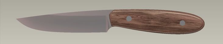
Here is an example of a knife designed in CAD that I feel escaped the "cad design" look fairly well:
http://i566.photobucket.com/albums/ss107/Nathan_the_Machinist/wip_thread/cadknife.jpg
But I set out with a design on paper and a plan in my mind to achieve the look I wanted, without letting the CAD tool just do whatever.