- Joined
- Dec 14, 2009
- Messages
- 135
Sure, not at all. Mine was just a cautionary tale. If you're doing it right, you're doing it right.
Re: your "challenge"
Here is an easy one. It is easy to do well, it would also be easy to do badly.
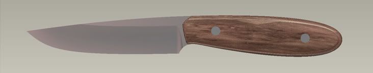
Trace that and I'll give you my opinion of your efforts. :thumbup:
Though I'll point out, my concern is more about creating in the computer in the first place. For a lot of folks, is it an awkward canvas to create in , and it frequently shows...
Nathan,
I just logged in and found your post. I'll have you a DWG file in a few minutes.