Forging press opinions wanted.

Joined
Aug 13, 2022
Messages
134
Hello Again
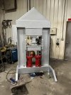
I am in the process of building a forging press. it will end up in the 24 25-ton range.
I have all my pump, motor cylinder stuff worked out. Thanks to all your help, a few books and my local Hydraulic shop.
The one thing I am still in the air about is do I want my ram pushing down or pushing up into a stationary upper die.
I am interested in opinions of anyone using either system and the pros and cons they see in each design.
I am more inclined to build one that the ram pushes down onto a stationary lower die but hey I'm open to advise and opinion.
Thanks Jerry
 
If the ram is on the top, all the hot scale, slag and flux misses the cylinders and hoses.

If the ram is on the bottom, you can do a guard to cover that and keep the weight and overall height low.
 
I've built presses both way and I prefer the ram pushing up. Height of either of the presses was of no concern to me but if height matters then for sure go with ram on bottom pushing up.
Here's a picture of the new press I'm building now.
Jim
 

Attachments

  • IMG_8171.jpeg
    IMG_8171.jpeg
    675.6 KB · Views: 9
I've built presses both way and I prefer the ram pushing up. Height of either of the presses was of no concern to me but if height matters then for sure go with ram on bottom pushing up.
Here's a picture of the new press I'm building now.
Jim
That's a Monster
 
Last edited:
Boat builder.
Since you have built a press or 2 I have a dumb question well 2 questions. 1 to get the PSI range I want ( in the CYL) I am looking at a 4X10 cylinder that will run up to 3500 psi . that's all good .
Question is will the IPS. slow down with a bigger Bore?????as more oil need to push or is that variance nominal??
Next and Mabee I'm way over thinking this but all the cylinders I see of this type have a column load of 37,000 lb.
The 5hp 220 motor at 3450 RPM and the 16 to 22 Gpm. pump should get around 24 to 25 ton ( Still debating Cylinder original calcs was for a 2x10) so do I not want the column load to be at least 50,000 lb?????
Or am I missing something Important.
Can you recommend a mod. number and supplier of the cyl. that will run 25 ton??
Thanks Jerry
 
I prefer the ram pushing down on a stationary die, I think you have more control when you can hold the part still on the stationary die and see what you are doing a bit better as you lower the ram. The reverse I don’t feel like I have as much control when working quickly.
 
I've never used an upwards pushing press, but it seems like pushing down is just more natural - perhaps for the reasons Joshua mentions?

Have you looked at these two on-line calculators?
and for speed

You're going to need at least a 5" cylinder to get 25 ton with 2500 psi. While a cylinder or pump might be rated 3500 psi I wouldn't try much in excess of 2500 psi, or at most 3,000 psi. Note with a 4" cylinder it takes 4,000 psi to get the 25 ton desired.

With a 5" cylinder your 16 gpm will provide a good 3.2 inch/sec of speed. Even 2 in/sec is ok, but 3 or greater is really nice.

Are you planning an "H" style frame or a "C" style? Both have pros and cons

Good luck and have fun.
 
I prefer the ram pushing down on a stationary die, I think you have more control when you can hold the part still on the stationary die and see what you are doing a bit better as you lower the ram. The reverse I don’t feel like I have as much control when working quickly.
I thought the same but now after having both I prefer the push from the bottom.

Great info Ken. Just fill in the blanks and it tells you everything you need to find out what cylinder size you need to get what you're looking for.
 
I've never used an upwards pushing press, but it seems like pushing down is just more natural - perhaps for the reasons Joshua mentions?

Have you looked at these two on-line calculators?
and for speed

You're going to need at least a 5" cylinder to get 25 ton with 2500 psi. While a cylinder or pump might be rated 3500 psi I wouldn't try much in excess of 2500 psi, or at most 3,000 psi. Note with a 4" cylinder it takes 4,000 psi to get the 25 ton desired.

With a 5" cylinder your 16 gpm will provide a good 3.2 inch/sec of speed. Even 2 in/sec is ok, but 3 or greater is really nice.

Are you planning an "H" style frame or a "C" style? Both have pros and cons

Good luck and have fun.
Hello and thank you for the reply.
Your answer is exactly the opposite of what I thought. . where I thought larger cylinder more vol there for less delivered tonnage. Thats my curse being a plumber I am always applying the wrong fluid dynamics.
So 5 inch it is, and I am building an H frame. The c is great but its logistics getting that giant 1 1/4 plate to and from my water jet cutter at work to home. H frame i can collect the smaller parts. More easily and assemble at home.
My frame was going to be 4 1/2" X4" angle irons with a 1-inch gap between them ( or whatever the spread is on my yoke) To make the slot run the ram in .
and then obviously header and bottom out with 1 inch or larger plate. ( I have up to 2 inch )Does that sound beefy enough???
Thanks Jerry
 
And again, thanks for the help I have a 5X10 2-inch shaft double acting cylinder so that's what I will use. I don't have my pump yet so should I go with 16 Gpm or should I go lager??? Thanks Again
 
16 GPM will give 3.2 in/sec which pretty decent and will work just fine. BUT - a tad faster would be better and since you're looking for a pump I'd look at a 20 gpm pump to give almost 4"/sec which is nice. Remember to check RPM spec on the pump. They might give 20 GPM at 3600 rpm which would be good with your 3600 rpm motor. I think you said you have a 5hp 3450 rpm motor on hand? Good motor for the press.

On the crossbar- 1" depending on how wide it is. For 16 ton a 1"X4" bar works pretty good per calculations. For 25 ton I might 1-1/2" X 4". You do need to consider your cylinder how wide the yoke is for fitting over the bar.

How thick is the angle iron? Here's a calculator you can do some stress calculations.

Here's a neat beam deflection calculator for the crossbeam with explanations on how to use it:
https://www.omnicalculator.com/cons...#how-to-calculate-the-maximum-beam-deflection

You might need this calculator also:
 
Last edited:
16 GPM will give 3.2 in/sec which pretty decent and will work just fine. BUT - a tad faster would be better and since you're looking for a pump I'd look at a 20 gpm pump to give almost 4"/sec which is nice. Remember to check RPM spec on the pump. They might give 20 GPM at 3600 rpm which would be good with your 3600 rpm motor. I think you said you have a 5hp 3450 rpm motor on hand? Good motor for the press.

On the crossbar- 1" depending on how wide it is. For 16 ton a 1"X4" bar works pretty good per calculations. For 25 ton I might 1-1/2" X 4". You do need to consider your cylinder how wide the yoke is for fitting over the bar.

How thick is the angle iron? Here's a calculator you can do some stress calculations.

Here's a neat beam deflection calculator for the crossbeam with explanations on how to use it:
https://www.omnicalculator.com/cons...#how-to-calculate-the-maximum-beam-deflection

You might need this calculator also:
Thank you for those charts they are extremely helpful.
The problem I am having (or at least think I'm having is. My motor is a 56 Frame.) I was wanting a 56C or 184TC in 5 horse 220V, 3460 RPM, they don't exist there is 1 on amazon and its always out of stock. do you see an issue of just using the 56 frame and making a bracket to line the pump to the motor??? I forgot the name for the shaft couplers with the rubber star in them.
 
Lots of pumps are just mounted to the shaft with flexible couplings. The motor is held fast by the feet and the pump has a bracket mounted to the same plate as the motor feet.
Also, many motors that are just listed as 56-Frame have faceplate "C" mounting holes.
 
Simple Formula for Calculating Elongation

Elongation = (L × F) ÷ (A × E), in which:

L is length, in inches
F is applied force, in lbs.
A is cross section, square inches;
E is modulus of elasticity (from table)
Elongation will come out in inches.

Let's take the Coal Iron so called 12 ton press which is only 9 ton with the 3" cylinder it's shipped with at 2550 psi. The frame is 2" angle at 1/4" thick about 30" long.

The 4 angle irons make a bar 1"X4" or 4 sq in so for Coal Iron's 9 ton press (ships with 3" cylinder at 2550 psi) we have
(30 X 18,000) / (4 X 30,000,000)
540,000/120,000,000= 0.0045" of stretch.

I have changed the 3" cylinder Coal Iron shipped with my press to a 4" cylinder so where I to push the press to 16 ton (NOT recommended) we would have .008" of stretch. Interestingly, the calculator on the page I linked to gives the same answer. Isn't it neat with math works? :)

With your 4"X4" angle if it's 3/8" thick that should give a bar about 1.5"X8" or 12 sq in. At 25 ton you should have around 0.004" stretch, same as Coal Iron's 9 ton press so I think that would be good. Even 1/4" thick 4" angle would give a 1"X8" bar for 0.006" stretch in 30" which is the same as Coal Iron's 9 ton press "IF" it actually gave 12 ton. Remember, those amounts of stretch are for a 30" length. I'm sure you'll have at least 36" or perhaps 40" which will change the amount, but not the percentage. Also, these numbers are based on the force being in the center of press. Sometimes you might have the billet to one side, especially if the dies are 6" wide. This would put more pressure on one side than the other and would cause it to stretch more. I would think 3/8" thick angle would be good, but 1/4" marginal. Comments from other folks please.

Hopefully other folks are checking my math to be sure I didn't miss anything.

Yep, with a 56 frame motor that doesn't have the 56C mounting holes you'll need a base plate to mount the motor and pump to. The pump will need a spacer to allow aligning the pump shaft to the motor shaft and those do need aligning pretty darn close. A 56C sure does have to allow the mounting bracket that bolts to the 56C, and the pump mounting to the bracket. Those provide shaft alignment.
 
Simple Formula for Calculating Elongation

Elongation = (L × F) ÷ (A × E), in which:

L is length, in inches
F is applied force, in lbs.
A is cross section, square inches;
E is modulus of elasticity (from table)
Elongation will come out in inches.

Let's take the Coal Iron so called 12 ton press which is only 9 ton with the 3" cylinder it's shipped with at 2550 psi. The frame is 2" angle at 1/4" thick about 30" long.

The 4 angle irons make a bar 1"X4" or 4 sq in so for Coal Iron's 9 ton press (ships with 3" cylinder at 2550 psi) we have
(30 X 18,000) / (4 X 30,000,000)
540,000/120,000,000= 0.0045" of stretch.

I have changed the 3" cylinder Coal Iron shipped with my press to a 4" cylinder so where I to push the press to 16 ton (NOT recommended) we would have .008" of stretch. Interestingly, the calculator on the page I linked to gives the same answer. Isn't it neat with math works? :)

With your 4"X4" angle if it's 3/8" thick that should give a bar about 1.5"X8" or 12 sq in. At 25 ton you should have around 0.004" stretch, same as Coal Iron's 9 ton press so I think that would be good. Even 1/4" thick 4" angle would give a 1"X8" bar for 0.006" stretch in 30" which is the same as Coal Iron's 9 ton press "IF" it actually gave 12 ton. Remember, those amounts of stretch are for a 30" length. I'm sure you'll have at least 36" or perhaps 40" which will change the amount, but not the percentage. Also, these numbers are based on the force being in the center of press. Sometimes you might have the billet to one side, especially if the dies are 6" wide. This would put more pressure on one side than the other and would cause it to stretch more. I would think 3/8" thick angle would be good, but 1/4" marginal. Comments from other folks please.

Hopefully other folks are checking my math to be sure I didn't miss anything.

Yep, with a 56-frame motor that doesn't have the 56C mounting holes you'll need a base plate to mount the motor and pump to. The pump will need a spacer to allow aligning the pump shaft to the motor shaft and those do need aligning pretty darn close. A 56C sure does have to allow the mounting bracket that bolts to the 56C, and the pump mounting to the bracket. Those provide shaft alignment.
Thank you for the help. It makes 100% sense. I have 1/2 X4 inch angle so should be good there @25 or so ton.
Another Dumb Question >>>>>> what is the recommended width between the uprights on the frame? As I am sure with everything being constant the wider, I go the more deflection on both the uprights and the top Cylinder mount. I was planning between 14 and 18 inches between the uprights. (working area) any insights here??? I could draw a little Diag. if that would help visualize my plan.
Thanks Jerry
 
Lots of pumps are just mounted to the shaft with flexible couplings. The motor is held fast by the feet and the pump has a bracket mounted to the same plate as the motor feet.
Also, many motors that are just listed as 56-Frame have faceplate "C" mounting holes.
And thank you Stacy
That is what I am going to do, simply build a mount for both motor and Pump. I have zero Idea why A 5Hp 220V 3400 rpm 56C motor is Just not available? There are Same specs and 56 Frame motors everywhere but No 56C. Go Figure.
With the pump single or 2 stage????
Thanks Jerry
 
Looks like with 4"X1/2" angle iron you could go 50 ton with no problems since you're using 4 of them. That's 2 angles on each side?

How much space between them for crossbar thickness - first look at how wide the connection is on the ram. First thing is to decide on the connections you have on the cylinder ends. Typically I think the TieRod ends are what's normally used for presses. But, do remember, I'm VERY limited in my knowledge of different presses.

I looked around some for 5" cylinders but didn't find what I was looking for to tell how wide the tieron end was to fit over the crossbar. Here is the one I did find:

I think you might find 18" outside to outside measurement a good goal. The angle iron will take up 8" of space (4" on each side) leaving 10" inside clearance. The 5" cylinder is going to be at least 6" leaving only 2" of space one each side of cylinder. That also gives plenty of width for the dies.

On the crossbar, the cylinder linked above has 1.13" which is just right for a bar 1-1/8" thick, but I suspect that would be hard to find. Perhaps you get get a 1-1/4" thick bar and mill down a spot for the tierod end? If so that would be nice. Looks like a 6" wide bar would give only about .050" deflection at the full 25 ton. An 8"X1-1/8" bar would give only .037" deflection at full 25 ton. Those numbers are using the calculators linked above.

DO REMEMBER I'M NOT AN EXPERT SO THESE NUMBERS SHOULD BE CHECKED!!

Single stage or 2 stage pump. It seems most presses have a 2 stage, but I know of one press that uses a single stage and the owner swears it's by far the best. I think the 2 stage are more economical. 2 stage is what's mostly used so the ram travels fast under low pressure when ram is moving up 'n down. When the die touches the billet and pressure builds to 600 or so psi, it kicks into low speed to handle lots of pressure. I can't see why low speed hurts then since it's seldom moving more than a 1/4" or so - sometimes less.
 
1st of all Ken
Thanks for your help what you have done is given me points to look at things to worry about. and I realize they are suggestions use at my own risk.
With that being said here are a couple quick scrawling's of what I have in mind. 4 4X1/2 angles the plate in the middle will be whatever width the yoke is .
All the seams or joints will be welded as well as a 3/4-inch grade 8 bolt to provide a mechanical component.
The second pic is of the cross piece for the yoke attachment point and the 2X9Xsay 18 cap on the top of that boxed out at the Angle Iron.
over built ya but its the materiel I have on hand. I don't suspect any or at least very little deflection.
The bottom ( for lack of better terPress 2.jpegm ANVIL) will be built the same with easily removable dies.Press 1.jpeg
 
Back
Top