Grizzly 2X42 grinder

I would expect most any 6" or 8" contact wheel would work just fine. Especially if the thicker tooling arm is in use. I just checked and a replacement tooling arm from Grizzly is only $10.70. plus shipping.
Where are you finding a replacement arm?
 
On the Grizzly webpage for the 2X42 grinder there's a link on the page under "Product Links", the "Buy Parts" has got the full parts and prices.
Oh, my mistake. I thought you meant it was an aftermarket tool arm that was a heavy duty version or something.
 
For an aftermarket tool arm just order a 1"X1/2" (or 1"X5/8") aluminum bar, then cut some spacers to make the grinder accept the thicker tool arm. I've got some 1/2"X1" aluminum bar in scrap pile if (when) I decide to change to a heavier tool arm.
 
I have an 8 and 12 wheel on arms for mine. For arms pops sales 5/16x2 5160 and I cut it to fit, drill and heat treat. 1 piece makes like 5-8 arms. For the 72" arms I weld a piece of 1/2 square on the left side for rigidity and I have had no tracking problems. But I did make a housemade type tracking adjustment for mine, so your mileage may vary. The wheels are the worst on the tracking and the reason I had to upgrade my adjustment. Although, I did buy the cheapest 60$ wheels I could get off eBay. I will also say mine is ugly as hell; I am more for function over form. But I will admit my Frankenstein is ugly.

As far as the motor, it's wired like a stepper motor and someone could probably add a switch to make it reversible with some aggravation; but, I'm really just waiting for it to die and install a 1.3hp from servomotorkit to it.
 
That's a servo motor you're looking at on servomotorkit site? I looked around on that site and didn't see any stepper motors, only servo motors which are better for this application. I sure wish I had known about servo motors when I changed out the 1ph motor on my Grizzly G0602 lathe and used a servo motor instead.
 
That's a servo motor you're looking at on servomotorkit site? I looked around on that site and didn't see any stepper motors, only servo motors which are better for this application. I sure wish I had known about servo motors when I changed out the 1ph motor on my Grizzly G0602 lathe and used a servo motor instead.
No, it appears from the wiring it is a stepper on the grizz, servo would be the upgrade. If you text the number on the website he will call you back, really nice guy. We spoke about 6m ago and I took measurements and he said he a 1.3hp that fit those measurements. This is going off memory, I could be slightly off. I thought this motor woulda took a shit way before now and I would remember what was going on. Maybe the electrical tape and rtv I put all over the bottom of the control box is more effective than I anticipated.
 
I stand corrected - you're right about the 2X42 motor - it is wired more like a stepper than a servo. I'd never really looked at the wiring on a servo, but looking at the 2 servos I'm running here they have the 3 wires, just like the wiring shown online for servo motors. The servo motors I'm using came pre-wired to controller box so I'd never really looked at the wiring, just connected the plugs.

A Bi-Polar stepper has 4 wires and a Uni-Polar has 6 wires. The servo usually has 3 wires, power, negative, and signal.
 
Last edited:
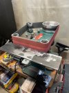
I move it 1/2” forward. Next move would be elongating the holes. Not having a mill makes for more of a challenge.

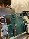
Does anyone know or can suggest where end of the platen should go? Should it be in line with the outside face of the upper idler wheel?

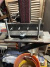
I did the fit up with the grinder in the horizontal position. Spring clamps worked well to position the pieces . The mounting bolts holes were drilled and threaded 1/4”x20. These pass through the spacers.

Truthfully, it’ll probably see little use for me but any mod is cool and to cobble it together with crap on hand ? Better .
 
Does anyone know or can suggest where end of the platen should go? Should it be in line with the outside face of the upper idler wheel?
Are you referring to the platen you mounted on top between the top idler wheel and tracking wheel? If so, then it depends on what you wish to accomplish. "IF" you're planning for lengthwise grinding (really good) then the edge of the platen next to the top idler wheel can be raised up at least 1/2" (or more) and put a radius on the edge of platen. This allows a nice edge to grind the plunge line. If you're looking at no plunge line then allow the platen to be flush with the top of wheel.

You will be very happy with the results of lengthwise grinding.
 
It will create a lot of friction at the forward edge as it is shown in the photo. Like Ken said, sometimes you want that ... but normally it should be in a perfect line between the wheel tops. Lay a straight edge across the wheels when aligning it and adjust to just barely touch that line.
 
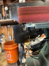
Played around a bit more the the water fall platen. I tacked on another piece of steel on top of the existing one and also lengthened it to over the top idler. This set up would not work with the tracking wheel guard nor a 42” belt. Luckily, it was easy enough to grind away the welds.
I also discovered all I need was to adjust the idler back under the edge of the platen. Here I needed to compress tension and adjust at the same time.
I believe I’ll leave as is.
 
I believe the idea of a "waterfall" platen is to make a consistent radius to touch up the plunge. At least that's how I've seen it used.

It's supposed to be shaped like a "waterfall" where the belt is the "water" and the platen is the "cliff".

The belt moves around the edge of whatever radius you've set on the edge of the platen, then moves at 90° to the platen's surface, so you get a nice even radius at the plunge, while maintaining a 90°plunge line.

If you were going to use your current setup like that, you'd have to remove the front wheel, or extend the platen significantly, so the belt drops of the "cliff".
 
Yes, what he has in not a waterfall platen. When making a waterfall platen, the edge needs to be radiused a little bit to allow some degree of smoothness or it will destroy the belt fast. As Andy pointed out, the end of a waterfall platen needs to allow the belt to turn 90° to fit the plunge at the ricasso or bolster.

What he has make I call a sharpening platen, or upper platen. It gives a short area to sharpen the knife with good control at slow speed. It works especially well with a reverse function VFD. A sharpening jig makes it almost foolproof.
I show some photos and give info in this thread:

I have used a flat glass platen with no top and bottom wheel, with the ends radiused on a 400-grit belt with good results. You MUST use slow speed!

My suggestion to make a waterfall platen is to build a flat platen with a 1/4" hardened steel top roller and bottom roller. I built one years ago for my Bader that used my 1/4" small wheel. It worked, OK, but got very little use. I gave it away with the Bader. Maybe I'll build another and post the build. It also MUST be run slow.
 
Last edited:
Kinda like the idea of buying one and setting it up as a strictly horizontal grinder.
 
Back
Top