LeadingEdge V-Sharpener for any 6 inch stones - Sneak peek

Show of interest

  • Yes

    Votes: 29 82.9%
  • No

    Votes: 3 8.6%
  • Maybe

    Votes: 4 11.4%

  • Total voters
    35
gotta say this looks sweet. I'd like to see resolution of angle higher then 5, 1 degree would be great, 2 or 3 degrees would let hands know how system and pressure limits were? Any idea what gritomatic's time to market is? Thx for extending out length of stone. REALLY useful for building SIC stone set for s30v and below, With maybe a coarse diamond hone to start reprofile, like AG Russel n Ron at KME do.
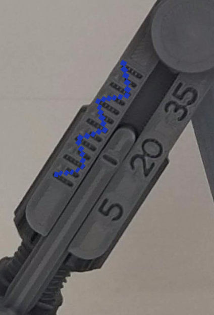
The scale lines will be notched every 2.5 degrees and it will be very easy to adjust your angle between the resolution lines. With a minute or two of using the system, you can easily adjust in 1 degree (or less) increments.

With the limits of 3D printing, I can't add too many lines and text or it won't be properly visible. Having 2.5 degree lines from 5 to 35 degrees seems to be about the limit of what works well with the small size of the guide. Of course, using a digital angle cube will be the most accurate way of doing things but I think it's largely irrelevant because it's unlikely that anybody would be able to hold a knife 100% accurately straight, down to half a degree during the entire sharpening process.
 
I'm getting close to the final version of my angle guide. It's very easy to set an exact angle to the degree - below are some pics. The scale is from 5 to 35 degrees. Long lines are 5 degree increments and the short lines are 2.5 degree increments. The width of each line is 1 degree.

If I manufacture it in a slightly darker color (like the titanium/grey color of the other parts, then the lines will be much more visible. I only made this one in white because it's a test part for my own use. It will have 2 angle guides when done - one for each stone holder. I'm also planning on making the angle adjusting nuts a little bit bigger.

Here is a pic with the angle set at 15 degrees. First pic is the scale and second pic is of a comparison with a digital angle cube:

IMG_20220819_174344.jpg

IMG_20220819_174325.jpg


Now, as an example in the the next pic I set the angle to 14 degrees. The width of the line in the centre guide is equal to 1 degree, so setting it a line width short of the 15 degree mark, gives you exactly 14 degrees. Any angle can be set this way very accurately.

Untitled.jpg

With the next change, I plan on replacing the scale lines at the bottom with angle numbers. I think where I have the numbers printed in the above pics could be confusing and could be misinterpreted. I plan on having "5"; "20"; and "35" digits at the bottom. That's about all I can fit with the print resolution.
 
Last edited:
I don't know whether this helps, but since each increment between lines(both long and short) is 2.5 deg, will it be possible to have all the long lines above, and short lines at the bottom?

So the top long lines will mean 5, 10, 15, 20, 25, 30 and 35 per side, while the bottom short lines will indicate 7.5, 12.5, 17.5, 22.5, 27.5 and 32.5. I think most folks are used to 15 and 20 deg per side from Sharpmaker, and having the integer numbers on top probably is easier to read.
Thanks for helping out with input comis comis . As a matter of interest, I did that initially but with the size of text needed I changed the design a bit again to now have numbers at the bottom and the scale at the top. Looking at it as someone who sees it for the first time, makes more sense logically. I'll post photos when done. :-)
 
As long as it is easy to read, its good knowing a hash mark is ~ 1 degree, but I was facinated by the abacus, slide rules, Reverse Polish Notation, Scientific Notation, Avagadro's constant, etc...
Teacher in me says "put the cookies on the lowest shelf," if PLA material resolution is 1 degree, use printed sticky or aluminum laser printed card appliqued to your angle bar for larger eaiser to read instant angles. I'm planning to put small bubble levels for quick base leveling. I would be very happy to pay for multiple materials and labor.

Have you had any time to investigate aluminum and titanium 3D Printing?
 
Have you had any time to investigate aluminum and titanium 3D Printing?
I would absolutely love to print all of my designs in metal; especially the knife clamps I designed for some of my other systems. Metal 3D printers (at least for now) are still above my level of affordability, they are still very expensive. Only really a feasible option for the major manufacturing industry. Give it a few years, and hopefully the price of metal printers will come down significantly! I hope!
 
Last edited:
I've completed the final version of the angle guide. Let me know your thoughts an input.

For best readability, I've only added 3 numbers - 5; 20 and 35. Looking at the scale, the rest is obvious...I hope :)

View attachment 1905061

That's nice, I think it should be pretty much self explanatory. For even easier understanding, user could always fill in the 5/20/35 and relevant marks with white ink.

This looks quite ready, just a very minor question--if the user try heavy reprofiling with a larger knife with wider/thicker coarse stone, will the system womble/move since it maybe a little top heavy? I find this happen from time to time on a Sharpmaker, if I weren't paying attention and not holding onto the system itself during the sharpening.

User could always affix the whole thing onto a piece of wood, but I'd rather to keep it mobile like a Sharpmaker.
 
... just a very minor question--if the user try heavy reprofiling with a larger knife with wider/thicker coarse stone, will the system womble/move since it maybe a little top heavy? I find this happen from time to time on a Sharpmaker, if I weren't paying attention and not holding onto the system itself during the sharpening.

With heavy bench stones, a lot of force or being over-eager it may move around a bit. In a case like this, you can stabilize it with a G-clamp if you find you're getting tired of holding it steady with your non-sharpening hand.
 
Metal 3D printers (at least for now) are still above my level of affordability, they are still very expensive.
I hear that!
Some kind of shared resource venu is what happens, incubators, various schools, kind of like sharing time on robotic telescopes, scanning electron microscopes, main frames, etc, very expensive tools sometimes require sharing early on.
Let me know your thoughts an input.
the different color PLA is much sharper! Excellent.

As a practiced hobyist, I quickly navigated your angle guide, with first few passes taking about a minute to comprehend and be confident that I can use angle guide:
1) by remembering angle guide spec for long n short hash's, hash itself, and range (quickly glimpsed by added numerical alignment bar);
2) then counting down on (left) hash bar one by one, from nearest number from number bar, to angle you set in pic;
3) then jumping around associating numbers to long hash marks and chunking by 2.5 to get to 1 degree wide hash marks (I had to magnify pic to see 1/2 degree association with both hash marks you set angle for pic)... a small magnifying loop over set bar hash, big enough to go over slide line to hash bar???

Why the difference of placement for your 3 bars on each base and stone holder?
For multiple reasons (language, practice, prior-knowledge, etc), including pre-conceptions and bias, I like Right assembly's visual cue for angle, where set bar origin is located on stone holder, over Left assembly set bar being located on base. The number and hash bars should both be located on base. Both numerical bars should arc with same degree sequencing, not opposite.

My first user will be a rookie coming off p@4#-thru's (sharpener that will not be named ha ha), and upper hash mark line associating with set line and lower numerical line harkens back, in terms of cognitive load, to another day then today or tomorrow.
I would like a wing added above top hash line facing user, to afix printed cheat sheet. Or, is there enough width, front to back, for me to raise above hash line, by gluing, a plastic or aluminum cheatsheet (my assumption is that you can glue stuff to PLA), to assist my new user?
Are hash marks deep enough to add color code? What paints stick to PLA?
 
I hear that!
Some kind of shared resource venu is what happens, incubators, various schools, kind of like sharing time on robotic telescopes, scanning electron microscopes, main frames, etc, very expensive tools sometimes require sharing early on.

the different color PLA is much sharper! Excellent.

As a practiced hobyist, I quickly navigated your angle guide, with first few passes taking about a minute to comprehend and be confident that I can use angle guide:
1) by remembering angle guide spec for long n short hash's, hash itself, and range (quickly glimpsed by added numerical alignment bar);
2) then counting down on (left) hash bar one by one, from nearest number from number bar, to angle you set in pic;
3) then jumping around associating numbers to long hash marks and chunking by 2.5 to get to 1 degree wide hash marks (I had to magnify pic to see 1/2 degree association with both hash marks you set angle for pic)... a small magnifying loop over set bar hash, big enough to go over slide line to hash bar???

Why the difference of placement for your 3 bars on each base and stone holder?
For multiple reasons (language, practice, prior-knowledge, etc), including pre-conceptions and bias, I like Right assembly's visual cue for angle, where set bar origin is located on stone holder, over Left assembly set bar being located on base. The number and hash bars should both be located on base. Both numerical bars should arc with same degree sequencing, not opposite.

My first user will be a rookie coming off p@4#-thru's (sharpener that will not be named ha ha), and upper hash mark line associating with set line and lower numerical line harkens back, in terms of cognitive load, to another day then today or tomorrow.
I would like a wing added above top hash line facing user, to afix printed cheat sheet. Or, is there enough width, front to back, for me to raise above hash line, by gluing, a plastic or aluminum cheatsheet (my assumption is that you can glue stuff to PLA), to assist my new user?
Are hash marks deep enough to add color code? What paints stick to PLA?
Paint works fine on PLA, even sharpee works if you wanted to mark it.

The lines and text are 1mm deep, so you could even paint some nail polish or colored epoxy in them and sand off the excess for some nice definition.

It's actually a lot easier to see in real life than in the pics I posted, so a loupe should not be necessary, it's big enough to see very clearly.
 
Last edited:
Hi
Hash marks and 1° steps?
Good idea, but unfortunately the manufacturing print resolution (taking into consideration print time and cost effectiveness for Gritomatic) won't work well and doesn't look good with anything more detailed than the lines the way they are right now.

Another point to note for interest sake, is that in reality, it's very unlikely for someone to hold and sharpen a knife by hand on a V sharpener with less than 1 degree accuracy. The accuracy you're able to set on my V sharpener is likely too high for most people already as the knife is held by hand. But it's nice to know you can set the angle the way you want it. :-)
 
Last edited:
Why the difference of placement for your 3 bars on each base and stone holder?
For multiple reasons (language, practice, prior-knowledge, etc), including pre-conceptions and bias, I like Right assembly's visual cue for angle, where set bar origin is located on stone holder, over Left assembly set bar being located on base. The number and hash bars should both be located on base. Both numerical bars should arc with same degree sequencing, not opposite.

I missed answering this question, sorry!

The different placement is merely to standardize parts. If I make the placement the same for the left and right guides, then there will have to be 2 different angle guides as opposed to 1 interchangeable guide.

I considered making a separate guide for left vs right but for Gritomatic cost & parts wise and for simplicity, it works better with less parts. If a user really prefers the look of the left guide, he/she could always turn the right one upside down, or place it on the opposite side of the stone holder.
 
standardize parts
Sweet glad I can flip it... and add color code, and bubble levels horizontal n vertical for base... and ?

Talked to the friend who is hopfully getting a unit, and told him I was enjoying the process of staring and giving you feedback on your 3D printed any-stone-V-sharpener ("like a Sharpmaker but not wedded to triangle stones"), he got it. A process I, or my brains dusty well trod trails miss. I told him about my team helping place one of the first $65,000 US dollar 3D printer's at a rural community college back in the day. And here you and many others (thingiverse) are inventing, replacing, improving, mashing up generally, with the tech. Good stuff, if the river don't rise n the LORD don't come yet (again:-)).
 
I'm getting close to the final version of my angle guide. It's very easy to set an exact angle to the degree - below are some pics. The scale is from 5 to 35 degrees. Long lines are 5 degree increments and the short lines are 2.5 degree increments. The width of each line is 1 degree.

If I manufacture it in a slightly darker color (like the titanium/grey color of the other parts, then the lines will be much more visible. I only made this one in white because it's a test part for my own use. It will have 2 angle guides when done - one for each stone holder. I'm also planning on making the angle adjusting nuts a little bit bigger.

Here is a pic with the angle set at 15 degrees. First pic is the scale and second pic is of a comparison with a digital angle cube:

View attachment 1904344

View attachment 1904343


Now, as an example in the the next pic I set the angle to 14 degrees. The width of the line in the centre guide is equal to 1 degree, so setting it a line width short of the 15 degree mark, gives you exactly 14 degrees. Any angle can be set this way very accurately.

View attachment 1904346

With the next change, I plan on replacing the scale lines at the bottom with angle numbers. I think where I have the numbers printed in the above pics could be confusing and could be misinterpreted. I plan on having "5"; "20"; and "35" digits at the bottom. That's about all I can fit with the print resolution.
Perfect!
 
Back
Top