PID Controlled Forge/Heat Treat oven plans & WIP

Joined
Aug 5, 2014
Messages
213
So after going through the stickys a couple weeks ago and finding all of the amazing plans for different PID controlled forges, tempering ovens, salt pot etc, I've switched gears fully to creating a really high-functioning PID controlled forge & heat treating oven.

First off, thanks to other members who shared all of their information on this, especially Stacy.

I won't be back home for another several weeks so at the moment I am in the planning & scheming phase, which has been a lot of fun. I won't rehash all of the information from other stickies but can provide links to other good threads and some condensed notes.

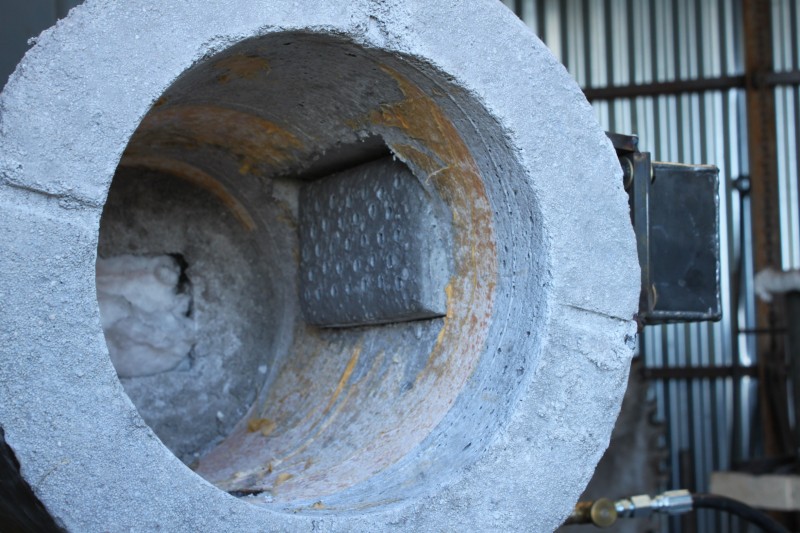
I'm interested in doing a 2-burner design. I mostly do knives, but would like for it to be large enough to do smaller swords as well, so what I'm thinking is a 12" by 24" body with either an 8" or 6" interior.

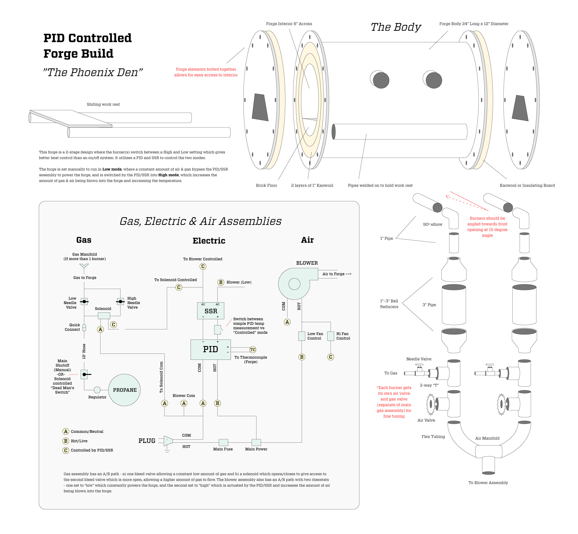
I designed out this "exploded view" of everything that needs to go into the forge. It's a work in progress in itself, as there are several areas that I'm still unsure about.

ePnxuIN.jpg


Here are some short bullets on the build/design:

• PID Controlled to switch between High/Low flame settings for maintaining temperatures (as opposed to gas switching on/off)

• I use mostly 220VAC so I will wire for that. Design can be adjusted easily for 110v

• 12” Diameter Tube 24” long

•*Front and back will be cut on CNC plasma or Water Jet

• 2 x 1" layers of kao-wool or ins-wool. 1/4" to 3/8"coating of satanite with a thin coating of ITC-100 over that

• Thermocouple - type K with 1/8" (8 gauge) lead size. Installed inside a ceramic TC sheath and the leads attached to a TC terminal block. Ceramic separators/insulators on the leads inside the sheath and the immediate area outside the forge.

• Blower between 70 and 150 CFM controlled by 2 separate Rheostats for High/Low mode

• Front opening of around 4" wide x 3" high and rear port approximately 3"x3"

• Burners will enter the chamber from the side at a tangent near the top, angled about 15 degrees forward. Either horizontal, or even slightly uphill toward the forge


Here are links to the main electronics and functional components: (I'm not affiliated with any of these companies just fyi ;))

PID controller with Ramp/Soak
http://www.auberins.com/index.php?main_page=product_info&cPath=1&products_id=4

Thermocouple
http://www.auberins.com/index.php?main_page=product_info&cPath=20_3&products_id=39

Thermocouple sheath
http://www.auberins.com/index.php?main_page=product_info&cPath=20_3&products_id=40

Thermocouple Connector
http://www.auberins.com/index.php?main_page=index&cPath=7_43

K type thermocouple extension wire, multistranded
http://www.auberins.com/index.php?main_page=product_info&cPath=7_35&products_id=179

25Amp SSR
http://www.auberins.com/index.php?main_page=product_info&products_id=9

220VAC Solenoid (Most people will probably want 110v for this one, and seems like a lot of people have also used 12VDC Solenoids)
http://www.ebay.com/itm/AC-220V-Water-Air-Gas-Fuel-Electric-Solenoid-Valve-G1-4-N-C-/281397079685?hash=item418492ae85:g:iBEAAOSwLVZVkd5g

Again, there are some areas of this that I'm not entirely sure of. If the electronics seem to not match perfectly I can adjust the design and reupload for others who want to use this design as well.

Several main questions I have are:

1) What should the burner spacing be on the burners? Suggested by Fred.Rowe --> Burners should be 4" on center

2) What does "com" imply in wiring diagrams? grumpy_grinder "means common or neutral wire"

3) Is an 8" Forge interior overkill? I'm just trying to build with future projects in mind so a little more than 6" sounds good.

4) I'd like to make this modular so any tips on being able to keep it upgradable/changeable are great!

Thank you again everyone, I will modify and add to this as I go. Looking forward to it!
 
Last edited:
Com is the common , neutral or ground. Who drew the electrical diagram? There's 2 components on the SSR? Am I reading this wrong?
 
Last edited:
Ok good to know. I drew the diagram based on things I found in other posts in the stickies but am probably wrong in a couple areas - my interpretation is that the SSR powers 1) the opening and closing of the solenoid and 2) The switching between the Hi and Lo mode on the fan.

In looking at this I also remembered that I didn't understand what the function of the "Switch Controlled" box is for between PID and SSR that Stacy had drawn in a sketch that he provided of the assembly, which is something I'd like to get clarity on as well ;)
 
I'm not sure why you'd have a switch there , isolate I would imagine. As long as you understand your schematic ... Because it doesn't really make sense. Make each diagram on a separate page. The solid state relay can switch one component unless you're going to parallel the output. You wouldn't want a drive to modulate?. You also get the benefit of added inputs and outputs from the drive if you wanted to add anything down the road. there are some issues with the SSR. Why use a relay for the solenoid? You can get them 24 volts DC and just use the DC from the drive put on a contact of the PID. Most controllers have 20/40 DC.
 
Last edited:
After thinking about it for a minute you want the high solenoid to be picked at the same time as the high speed setting of the motor? Or do you want independent control of the solenoid and motor?
 
Hey grumpy_grinder thanks for the replies and help ;) So essentially I'm basing this system off of the A/B blown forge that Stacy designed and other members have since built. One example is silver_pilates' build in the following thread:

http://www.bladeforums.com/forums/showthread.php/704470-Forge-Assembly-WIP

It essentially utilizes two potentiometers for fan control and two needle valves for gas control. The idea is that there is a constant "Low" setting that is manually dialed in with low gas pressure and low blower speed, which is your low-end temperature, and then a "High" setting that is activated by the PID which does two things: 1) opens the solenoid for the gas to flow through the 2nd needle valve, which allows more gas to flow into the setup and 2) Relays to the 2nd potentiometer with a higher setting which increases blower speed.

The idea with this setup (as I understand it) is that instead of the burner being an on/off function, it is high/low which gives more consistent temperature and prevents the "WHOOF" every time the burner re-ignites in an on/off setup

The 25 amp SSR is what seems to have been recommended for previous builds as well. In the link above, silver_pilate also has a diagram with the wiring that may help clarify.

And good catch on the 2 fuses - I'll remove that from the diagram ;)

Main power is just a safety shutoff option involving a solenoid that shuts off if there is a power outage, etc.

When I have time I'll go through and add more of this information back into the diagram above
 
i think what you are thinking of is a "close if fail" for the gas or in this case a normally closed solenoid. if there's a power failure there's no power to the controler. If anything you could have a start button on a Contact. latches when you start , picks off when you hit stop or power failure. So if power came back on everything doesnt fire back up.

I'm not saying you're wrong with the 2 fuses in series , just curious why 2?. I'm following this thread to satisfy my own curiosity.
 
Last edited:
I've not found a need for having two different controls on the fan. There is not enough variation between the high and low settings. The optimum is to set the low end gas needle valve, so that it results in a temperature just a few degrees below set point on the pid control. The air volume setting will be the same for both temperatures.

I think you will find that having a separate solenoid, in line, on the low gas will be much safer. If the power goes out the gas will close both solenoids, high and low. I put a green light, in line, after the switch that turns on the low end gas. When the gas is on the light runs green, when its off the light is off. Think dead man switching when building a forge like this.
My forge has three burners, each burner has a brass needle valve just before the burner goes into the forge. This makes tuning the forge easier. Each burner runs slightly different depending on its location inside the forge body.

Having openings at both ends makes the forge run more evenly. I run well head gas in my blown forge and found that putting a sliding door at the working end of the forge is useful. I slide the door so it covers 75 percent of the opening. It makes the forge heat up faster.

I have two forges that are built on this principle, they are worth the effort. Both of them hold their set point temp to within just 4 or 5 degrees.

Good luck in your build, Fred

Vulcan_s+Chariot-performance+sheet_+003.jpg

vulcan_s+chariot+002.jpg

Vulcan_s+Chariot-performance+sheet_+005.jpg

Vulcan_s+Chariot-performance+sheet_+006.jpg
 
I've not found a need for having two different controls on the fan. There is not enough variation between the high and low settings. The optimum is to set the low end gas needle valve, so that it results in a temperature just a few degrees below set point on the pid control. The air volume setting will be the same for both temperatures.

I think you will find that having a separate solenoid, in line, on the low gas will be much safer. If the power goes out the gas will close both solenoids, high and low. I put a green light, in line, after the switch that turns on the low end gas. When the gas is on the light runs green, when its off the light is off. Think dead man switching when building a forge like this.
My forge has three burners, each burner has a brass needle valve just before the burner goes into the forge. This makes tuning the forge easier. Each burner runs slightly different depending on its location inside the forge body.

Having openings at both ends makes the forge run more evenly. I run well head gas in my blown forge and found that putting a sliding door at the working end of the forge is useful. I slide the door so it covers 75 percent of the opening. It makes the forge heat up faster.

I have two forges that are built on this principle, they are worth the effort. Both of them hold their set point temp to within just 4 or 5 degrees.

Good luck in your build, Fred

Hey Fred thanks! Your Vulcan's Chariot forge is amazing, I had seen it in a previous post and I have to say, very inspiring!

The Dead Man's switch is a great idea, I will definitely implement that. Also interesting what you said regarding not needing the variable fan speed. That certainly makes the wiring and setup easier ;)

One thing that would be great to have your opinion on is, should I go for more than 2 burners? I'd like to not be limited by the size or burner capacity of the forge and am thinking that the 8" interior should be better than 6".

Three burners sounds fun, and your 5-burner setup looks awesome. I don't mind needing to use more gas, as long as it doesn't require an exorbitant amount of additional gas to power it.

Curious what your advice would be on these -

If I do a 24" length forge body, how many burners would you recommend?

Last, what burner spacing would you recommend and should they be oriented towards the front, center or back of the body?

Thanks again Fred
 
I'm not sure why you'd have a switch there , isolate I would imagine. As long as you understand your schematic ... Because it doesn't really make sense. Make each diagram on a separate page. The solid state relay can switch one component unless you're going to parallel the output. You wouldn't want a drive to modulate?. You also get the benefit of added inputs and outputs from the drive if you wanted to add anything down the road. there are some issues with the SSR. Why use a relay for the solenoid? You can get them 24 volts DC and just use the DC from the drive put on a contact of the PID. Most controllers have 20/40 DC.

Ok so I found this out regarding the switch between the PID and SSR ;) This allows you to switch between the two modes - 1) Simple PID temp measurement mode (no active control of burners, essentially manual mode+temp read) and 2) Being in "Controlled" mode where the SSR is activated and controls the forge functions.

As far as using a relay for the solenoid, I'm just doing what seems to have been recommended in various threads. Seems 25 amp SSR should do the trick for most purposes.
 
Hey Fred thanks! Your Vulcan's Chariot forge is amazing, I had seen it in a previous post and I have to say, very inspiring!

The Dead Man's switch is a great idea, I will definitely implement that. Also interesting what you said regarding not needing the variable fan speed. That certainly makes the wiring and setup easier ;)

One thing that would be great to have your opinion on is, should I go for more than 2 burners? I'd like to not be limited by the size or burner capacity of the forge and am thinking that the 8" interior should be better than 6".

Three burners sounds fun, and your 5-burner setup looks awesome. I don't mind needing to use more gas, as long as it doesn't require an exorbitant amount of additional gas to power it.

Curious what your advice would be on these -

If I do a 24" length forge body, how many burners would you recommend?

Last, what burner spacing would you recommend and should they be oriented towards the front, center or back of the body?

Thanks again Fred

The five burners was overkill and unneeded. I capped off the two end ones and ran the three center burners. They are spaced @ 4" on center. It can be done with one burner, it just has to have enough capacity to carry the fuel/air mixture.
I do like having three burners because it spreads the heat out more evenly than a single burner would. In a horizontal forge its easy to get zones of heat, with one burner.

The burners in the chariot are spaced from the center. Most all the work is positioned against the left side wall, when facing the forge. That places the pieces in behind the burners, out of the direct flame. I use the wall itself to lean the blades against, which is very useful.

Regards, Fred

Ok perfect, great to know! 4" on center sounds good. Main thing I want is for it to also be able to run low if needed for annealing, etc (~1200F) but it seems from what I've read that blown setups can run super low. Oh, and I guess you can always just run 1 burner if desired, even if you have 3 :p
 
I have been busy, but wanted to answer some of the questions and comments.

The diagram looks excellent.

I don't think a ramp/soak PID will be of much use on a gas forge. The whole method of the fine tolerance is to set the LOW and HIGH just slightly below and above the set point.
Ramp/soak is used in electric HT ovens which go from cold to the set point as needed. All a forge needs is a set-point PID controller to hold one target setting. Now, if you plan on using things in a modular system where they may control different devices, then the ramp/soak controller may be worth it, as you could plug a HT oven into it.

The output of the SSR can control both the gas solenoid and the high fan control. They both open and close simultaneously.

The box marked "main power" is the master power switch. It should turn off all power to the forge if switched off.

Adding a master shut off solenoid in the gas line in from the regulator is a good back-up safety if you think a power failure could happen. It is an unlikely situation, but a properly designed gas burner system should have a fail-safe. Optimally, it should be feed voltage from the main power switch. Shut off the forge and the gas shuts off, too.

I agree with Fred that the air supply could be just set with the gate valve and will work fine at both Hi and Low. If the upper and lower gas needle valves are set to 100 degrees above and below the target, the atmosphere will vary only minutely. The difference in cost is small, but the Hi fan controller could be eliminated.

Fuses - There should be a main power fuse in the line as shown. Optimally, there should be a second fuse in the line to the PID. I used a 5 amp for the main and a 1 amp for the PID. The blower size and the solenoid draw will determine the size needed. If using 220 VAC as the supply, I prefer using a fuse on each leg for safety. Also, the main power switch should be a DPST for a 220VAC circuit. I also like to place the main power switch before the fuse.

Chamber size - unless the space is needed for a large Damascus billet, a 6" chamber is more than sufficient in most cases. The only case that favors a larger size is if there will be a muffle installed for HT.

I would have to look at my old drawings, but I think the notation "switch controlled" referred to the power feed to the gas solenoid and the HI fan control. It meant that the SSR switched them on and off.
 
Last edited:
Hey Stacy thanks for the reply, looks like I need to turn on my notifications to see that I'm getting responses on this!

Great info - I am interested in using the muffle for Heat treatment so I think I am going to do that option, bigger interior plus the muffle ;)

Though it seems that a lot of people are doing this successfully without the High and Low for the fan, I can't help but think I'd be missing out on some added control. I think I may still end up going to go for it.

Regarding the "Switch Controlled" on your diagram from some years ago, I think maybe it meant 1) PID-controlled mode actually controlling the heat of the forge vs 2) running the forge manually with the PID just displaying the forge temp. Is that right?

On your recommendation I ended up going with the simpler version of the PID here: http://www.auberins.com/index.php?main_page=product_info&cPath=1&products_id=3

This version doesn't have the ramp/soak but seems to have all of the functionality I'll need for the forge, even for HT.

Still have a week left before going back home but will start posting pics as soon as I start building this!
 
Additionally, I was recently at the California Blacksmith's Association spring conference and a guy there had a PID controlled forge with a ribbon burner. He said he can run his forge at 1/2 psi and get very nice controlled heat with the burner.

I read more on it and it looks like a great feature to have on a forge for getting really even heat across the interior. There's a nice DIY method for building the ribbon burner using a small amount of castable refractory and crayons. The crayons are mounted in a mold with even spacing, and the castable is poured around them. When the castable has set, the crayons are molten out of the burner head and it's ready to go. Main thing is that you need to have enough back pressure provided by the blower, merely an issue of using the right sized blower.

A lot of people seem to do 3 rows of holes very closely spaced, but I think I'll do 2 rows of holes spaced a little further apart to span the length of the forge.

Here is a PDF with instructions for the DIY ribbon burner, made by Wayne Coe:

http://www.waynecoeartistblacksmith.com/uploads/Ribbon_Forge_Burner.pdf

As well as some images of what it looks like, compliments of blacksmith.org and rexroatknives:

2517=913-Fig-9-w.jpg


IMG_9839-800x533.jpg
 
Back
Top