At this point I think I need to add some more information regarding the output of PID controllers, and then get a start on the integral term.
If we “get” what happens in the proportional band, then it should be clear that there is some mechanism for the PID controller to step down to lower levels of activity the thing it is controlling. The two ways (as far as I know) that they do this is to use a true proportional output, or to use “pulse width modulation.
In a way, true proportional output is the easiest to understand (but is much less common, and much more expensive). This is done by adjusting the output magnitude (typically the voltage of the PID control output) continuously to lower values. For example, if you are at the lower end of the proportional band, the output of the PID would be its full voltage (for current purposes, lets pick of a guess of 10 volts for “full” output). If you are 50% of the way down the proportional band, the PID output would be 50% of 10 volts (i.e. 5 volts). If you are 25% of the way down the proportional band below the setpoint, the output would be 25% (2.5 volts) and so on.
But because the actual output of the PID is not sufficient to drive most devices (like a pump, or a heating element, or a valve), you need some sort of “translation device” between the PID and the thing being controlled. If you are driving a heating element, you would need a glorified transistor to take the low voltage coming out of the PID, and create a large enough voltage to drive a heating element (not practical). More practical is generating enough continuously variable voltage to drive a continuously variable valve (more doable). But that intervening amplifying equipment, and the continuously adjustable actuators (like a continuously variable valve) are expensive. Hence the use of pulse width modulation.
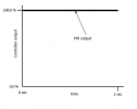
Lets take for example a control period (in the auber controllers called the Cycle Rate) of 1 second. In this case, if the controller was at the very bottom of the proportional band (or below that), the PID output is “full on” for every second out of every second (I know that is an awkward statement, but I am using it to set up what follows). This looks like this:

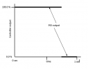
With pulse width modulation, instead of running the output at some percentage value of full for the entire second, is instead keeps the output “full”, but turns it on or off so that the percentage of time it is “full on” equals the desired proportion of the output. For example, if the PID is reading 75% downward in the proportional band, the output is “full on” for 75% of the time, and is OFF for 25% of the time:

When it is 50% of the way downwards into the proportional band, it is “on” for 50% of the time, and “off” for 50% of the time:

And so on….
You need, however, to keep in mind that as you get closer and closer to the setpoint, the duration of the “on” time can start getting really, really short (and the opposite at the far lower end of the proportional band). (also, there are some PIDs out there that might now split up the second this way, and instead have a sequence of multiple on/off cycles during the second, as long as the total proportion of “on” time is the correct proportion of the depth into the proportional band.
This kind of output does not work well for, say a mechanical relay, or a solenoid or a solenoid activated valve (which has a minimum activation time (something like 0.2 seconds or more) and which really do not like to cycle on/off at a fast rate). You can buy devices that convert the pulse width modulation to a continuously variable voltage output …. But again, these things are expensive.
This type of control output does, however, work really well for a heating element. In these there is no moving part that takes time to physically move back and forth, and quickly flicking back and forth between full voltage (to the element) and zero voltage is actually a pretty good approximation (in terms of heat output) to a continuously variable voltage applied to the heating element. The only concern here is that there is no way the output of the PID (a few volts) is enough to drive a heating element directly. It is enough (barely) to drive a mechanical relay (which can then switch on and off the higher voltage and current to a heating element. Several PID’s actually have alternate output connections with slightly higher voltages designed to be enough to directly drive a mechanical relay. HOWEVER, remember above it was pointed out that near each end of the proportional band the duration of either “on” or “off” times can get really short, and mechanical relays just are not made to react that fast (and can burn out prematurely if they are made to).
Hence the use of solid state relays (SSR’s) sitting between the PID and the a heating element. They are more expensive than a mechanical relay, BUT they have absolutely no problem handling on/off cycle times down into very small fractions of a second.
Now, lets get back to where this post started. When I originally mentioned the Cycle rate, I pulled out the example of one second. The problem is that this value is adjustable in most PIDs. For example, in the Auber controller, the cycle rate can be varied from 2-199 seconds (it does not go as low as one second). One of the very reasons this value is adjustable is in case a mechanical relay is used, you do not get in to situation where the relay is being asked to cycle on rates much less than one second (so for a mechanical relay, you would set the value much higher – 30 seconds of 199 seconds).
BUT, if you are, say, heating an oven – you have a problem. If you are 10% down into the proportional band, the intent is that the heating element will be on for 10% of the time. If, using the Auber example, you have the cycle rate set at the minimum 2 seconds, the heating element will be turned on for 10% of that (0.1*2s = 0.2 sec), then will turn off for the remainder of 1.8 seconds,
the controller will not act on any readings at all until that total of 2 seconds has elapsed. With the cycle rate set at maximum of 199 seconds, at 10% into the proportional band, the controller will turn on for (0.1 * 199 sec = 19.9 sec) and be off for the remaining 179.1 seconds, and
nothing will be done until that total of 199 seconds has elapsed.
There are different scenarios that can occur when you are lower down in the proportional band. One example is that you have an oven with a really strong heating element, and small proportional band, and a large value of the cycle rate. The oven will heat at full bore just fine, just not quite hit the bottom of the proportional band, continue heating at 100% for another 199 seconds, and fly right past the setpoint, still heating at full bore. Other variations are all over the place. Things that will increase the likelihood of instability are: small proportional band, large value of cycle rate, and an extremely powerful heating element relative to the insulation of the oven.
The bottom line here, I think, is that for most of what knifemakers there is absolutely no reason not to use the smallest value of the cycle rate that you can (unless you have something mechanical in the system that is being cycled on and off).
")