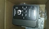
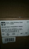
The VFD appears to be a nice unit. I went by what I had researched on here and bought what I think is the best. I will check and double check my wiring when I get to it. What I need at the moment is a guide to what spacers are need to line all my wheels up. I guess it all goes by feel. I turned down some bearing spacers last nite and made them different thickness. Center bearing spacer within the race area.
On my machine (which for clarification is my own design that is based on the EERF or GIB) I used the tracking wheel as my baseline, as this is the one that is most likely to be the farthest to the right. I used calipers to figure out how far it was from the arm when it's straight up and down. I used one machine bushing on each side of this wheel. use only the minimum thickness you need to do the job. Next, the drive wheel- using the measurement in the last step, I set the drive wheel the same distance from the main body, as this plane is the same plane as the arm (if it's mounted to the RIGHT of the main upright, if not, subtract 1". now that those wheels are in line, its on to the platen wheels (and large wheel if you are using them). Using the same measurement above, you should be pretty bang on with just one machine bushing on each side of the wheels. If not, and you need to add a lot (I did on my contact wheels), you can use a piece of 1/2' steel spacer tube. I miced it to a hair longer than i figured i needed, and ground it down to the right length from there. If it's not tracking well at this point, you may have a wheel out of plane. It's unlikely to be your drive wheel, so next check your platen wheels. First, make sure they didn't loosen up. If you tapped the holes, maybe they are not perfectly straight. Use a square to ensure the wheels are 90° to the platen C plate, or to the tooling arm, in the case of contact wheels. If they are off, just drill those suckers out with a 1/2" drill and use a through bolt and nut (loctight it later or do what I did and use nylock nuts) to secure. Don't crank them down hard. last is the most probable cause, but the hardest to fix, the tracking wheel. Did you think the holes you tapped in the tension arm were dead nuts on? You may be doubting that, and with good reason. Variance here can make a big tracking headache. the wheel needs to be in plane with the arm and this can get messed up by flubbing that tapping AND by flubbing up drilling the hole that contains the hinge pin, AND by flubbing the drill/ tap of the contact wheel axle hole. if it's out of whack vertically, it's not a huge deal, since this plane is adjustable (that's what the tracking is supposed to do). If it is out of plane in the horizontal, you can do a few things. First try flipping the piece that the tracking wheel screws into around. if tracking improves, leave it, if not, switch it back. you can loosen the screws that mount the tracking assembly to the arm and shim it out a bit with some flashing, or soda can material. you can also grind a machine bushing just a bit at an angle. If it's really bad, you can file the two mounting holes in the tracking assembly so you can rotate it a hair right to left. you may need to shim it before tightening it back up to ensure it doesn't move back. Sorry for the wall of text, but obviously, I've been down that road...