~$200 range disk sander

Also be careful with it.

I run mine horizontal, I feel this is more intuitive and safer.....

But I've Still have had Fudges when the knife gets sucked out, and my fingers go into the disk.

There are certain areas of the disk to be used, and certain areas to avoid
(Depending on Direction)

I'm on my 5th knife, maybe with it, and I'm still learning
 
Probably a stupid question but, I see the motor data plate says it’s 208-230v. My garage is standard 120v. Through how I wire the VFD this will be able to run?

I do have the manual for the VFD pulled up and I’m reading through it to make sure I’m understanding this all
 
The VFD runs on 115/120VAC singe phase.
The 3 phase motor runs on the three phase 230VAC that is made by the VFD.
Did you get a photo of the way I packaged the box?
 
The VFD runs on 115/120VAC singe phase.
The 3 phase motor runs on the three phase 230VAC that is made by the VFD.
Did you get a photo of the way I packaged the box?
I didn’t take a picture of how you packed it but I did get a picture after I moved a few things around to show my dad. I flipped the motor over, removed the plastic bag that was between the motor shaft and the wood, moved 2 blocks of wood out of the box (you can see them in the top of the picture I attached)

It was packed very solid, took me a bit to get the box open actually. Everything arrived intact and the box held up great. only bulged a little on the bottom.

 
The bulge was intentional because the motor was about 1/4" higher than the box was deep. I made a double wall box with the inner box glued to the outer box. That made the bulge about 1/2". All flaps were glued shut then the whole box taped with fiberglass reinforced tape in all directions.
Those wooden blocks are mostly unstabilized curly maple and some other woods. I usually use surplus handle material as packing. I think may be a block of something stabilized in the batch. IIRC, the plastic bag had a simple PID in it. Enjoy the disc grinder and the other goodies.

Funny story about shipping the box.
We have a lady at the PO who never smiles. She is polite and does a good job, but has a perpetual frown and dry demeanor. I took the box in and reached across the counter to set it on her scales because this was a HEAVY box. She gave me a sour look because I had reached into her space. As she droned on her spiel that she has to say for every package .... "Press the next button, ....can you verify the address, ....does it have......" she came to the question, "Is there anything liquid, flammable, dangerous, hazardous, ......" And I said Yes, but only if you drop it on your foot! It is a really heavy motor." She stopped and just stared at me, then suddenly broke out laughing. Pretty much everyone in the place started laughing, too. It was the first time I ever say her smile.
lol it’s always fun to get someone like that to laugh. I used to work in shipping/receiving at a factory back home. Me and the other forklift driver took great pride in our work, even if sometimes it wasn’t very glamorous. We over built crates, boxes, strapped and wrapped pallets beyond necessity. Mostly because it sucked when we’d get shipments of material or supplies and saw how shitty 99% of people/companies are at packing. So we wanted to show off to who ever was getting our parts… I guess parts getting there safe was nice too lol. So I can appreciate when a box is packed efficiently and in a strong way. Was happy to see I had to pretty much cut the top off of the box to get it open. I’d never seen anyone glue flaps on a box before, that was a pretty neat idea.

I love maple wood so I’m in heaven with all these blocks. I think the sycamore block is the stabilized one, it has some pretty cool grain to it!

I’ve a few quick questions about wiring the motor and VFD. I have it figured out how I wire them to each other. But I’m trying to figure out where in the circuit I want a switch to be, if any. The cart I use has a switched wired to the current motor on it so I can easily unhook that and reuse it when I remove the old motor. Do I want the switch connected to the VFD or to the motor?

Also I see people hard wire their VFDs to their circuit breaker. Im a little hesitant to do this since 1) We rent the house we’re living in and 2) circuit breakers scare me haha. So since the VFD is going to be 120v input is it safe to just wire it to a 3 prong plug? I figure this might be a little safer since if something goes wrong I can just unplug the thing.

And with that, the motor does not need to be plugged into an outlet or anything because it’s just wired to the VFD correct?
 
Put a regular cord from an old tool on the VFD to power it.
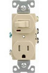
Plugging the cord into a switched receptacle is the simplest way to go.
There should not be a switch between the VFD and motor.
 

Attachments

  • 1698154104860.png
    1698154104860.png
    8.4 KB · Views: 0

So I have the motor opened up to get it wired and I see there’s no connector plates or anything for the wires. How exactly am I joining for example T1 and T7 to L1? And the left over T4, T5, T6 are they just twisted together and a wire cap threaded to them? Or are they each connected to the ground screw inside the back of the motor?
 
There should be a wiring diagram on the motor nameplate. If not, wirenuts work just fine for these low voltage (240vac) motors. I would use some electrical tape over the wire nuts. Yes, T4, T5, & T6 are twisted together with a wirenut. NO!!! They do not connect to the ground screw. That's for the green wire - well, ground wire anyway.

What I've written above should be checked with the nameplate wiring diagram
 

So I have the motor opened up to get it wired and I see there’s no connector plates or anything for the wires. How exactly am I joining for example T1 and T7 to L1? And the left over T4, T5, T6 are they just twisted together and a wire cap threaded to them? Or are they each connected to the ground screw inside the back of the motor?
Get some wago connectors, I like them Way better than twist wire-nuts
 
There should be a wiring diagram on the motor nameplate. If not, wirenuts work just fine for these low voltage (240vac) motors. I would use some electrical tape over the wire nuts. Yes, T4, T5, & T6 are twisted together with a wirenut. NO!!! They do not connect to the ground screw. That's for the green wire - well, ground wire anyway.

What I've written above should be checked with the nameplate wiring diagram
Thanks! That makes sense. I just twisted and capped T4,5,6 together so that’s taken care of. The second picture in the Imgur link has the wiring diagram. My problem is I don’t really understand how I’m connecting:
T1,T7 then to L1
T2, T8 then to L2
T3, T9 then to L3

I have a soldering iron and could solder then shrink wrap them, but I’m a little hesitant using such a permanent method.

I miscalculated and got a 3 cord wire only, which I need to connect the VFD to the cord. And found out I need a 4 cord wire for the motor to VFD. So I have to go back to the hardware store and get a section of 4 cord wire. Figure if I’m going to drive back I’ll figure out what kinda connectors or whatnot I need to connect the above mentioned wirings first.

I tried Google and YouTube but every single video or instruction I’ve found assumes I have a connector terminal built into the motor
 
Ooops, I never saw the 2nd photo with the wiring diagram. Yep, you've got it right,
T1,T7 then to L1 (twist 'n fasten all wires together, either wago, or wirenuts work if the HW store doesn't have the wago connectors.)
T2, T8 then to L2 (same as above)
T3, T9 then to L3 (same as above)

Do a search for "B09CKH8B5Q" on Amazon and a similar connector will come up. I've used those and they're good. For your use, wirenuts will also work just fine, and might take a bit less space inside the motor.
 
I snagged the wago connectors and some assorted terminal connectors. Also got the 4 cord wire. The smallest gauge they had was 12/4 so it’s a bit big for the amps but should still work. The wire from wall to VFD is 14/3.

Should have everything I need to get this all set up now, thanks guys
 
I forgot that the VFD I send probably does not have a reverse. I should have tossed in a switch. If the I sent VFD reverses, ignore the below.

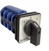
If you get a three-pole two position with center off rotary switch you can make the disc reverse easily. All that is needed to reverse a 3-phase motor is reversing any two wires.
Wire the three motor wires to it on one side as L1 - L2 - L3 and the other side as L2- L1 - L3.
The switch goes in the wires between the VFD and the motor.

The wires from the VFD go to the center lugs (common terminals). The motor wires go to switch position 1 as L1--2-3. Jumper from there to the switch position 2, as L-2-1-3.

When reversing, ALWAYS turn the switch to "0" and wait for it to completely stop before going to the reverse position.


(amazon )

Baomain Universal Rotary Changeover Switch SZW26-63/D303.3 660V 63A 3 Position 3 Phase​

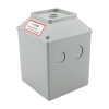
Get the box to mount it in from Amazon, too.
 

Attachments

  • h29a0uf3.png
    h29a0uf3.png
    174.4 KB · Views: 1
  • 8yxwf34b.png
    8yxwf34b.png
    122.7 KB · Views: 1
I didn’t get to finish setting it all up last night but I’m going to try and work on it a bit each morning before my next weekend. I’ll try to manage the wires in a way that it will be convenient to add a switch in later if it does not reverse
 
You will just cut the cord where you want to add the switch (with the power off!!!) Leave an extra foot or so in the cord for this later addition.

In the meantime, if the disc spins the wrong way for your setup, just switch any two wires at the VFD output to the motor.
 
Also, I wanted to say the other day, I can't remember if it was mentioned or not yet???

Your vfd prob wont work on ground fault protected outlets.
some garages, basements, and shops may have them.
you might need to swap out the outlet for an older, non protected style. It's easy.
 
Back
Top