-
All For Sale threads must have a pic showing the knife being sold with written date listed, your username & Bladeforums or BFC to prevent photo harvesting from elsewhere - scammers hate this one trick! The rules for The Exchange can be found here. Please read and follow them. Stop using Paypal Friends & Family and follow our best practices to prevent getting ripped off or having a bad deal.
-
The BladeForums.com 2024 Traditional Knife is available! Price is $250 ea (shipped within CONUS).
Order here: https://www.bladeforums.com/help/2024-traditional/
- The Knife Exchange
- KnifeMaker's Market: Knives & More for Sale
- For Sale: Knifemaking Supplies & Tools
You are using an out of date browser. It may not display this or other websites correctly.
You should upgrade or use an alternative browser.
You should upgrade or use an alternative browser.
2" x 72" Belt Grinder kit $369.99
- Thread starter wilhurley
- Start date
it looks great.
does this mean you have the scaled images of the original plans? given the relatively small package the waterjet was able to cut these out from, it would seem to be a very economical build. if I can ask, what did it cost you to have it cut out?
And I notice that for the motor mount you went with a circle and fixed spacing mounting holes rather than the original designs "x" grooves. I assume this is because you have the motor picked out. Do you think the X would weaken the frame?
Kindyr
No I do not have scaled images of the original plans. The concept was simple and I scaled my model off of my Bader B3 for dimensions.
The motor I am using is a 56 Face mount motor, therefore the hole and bolt spacing is compatible with that style motor.
I saw no benefit in the X groove concept. If one were to use 4 bolt bearings another plate several inches away would be necessary increasing the cost of the grinder and complicating the design.
I spent $250.00 for all the above parts to be cut.
Took about 2 hours this morning to drill and tap the 8 holes necessary to complete the grinder. I still must get the drive wheel and tracking wheels from Beaumont and also the motor. ALso need a few adjustable handles to adjust tracking and lock down the tooling bar.
Does anyone care to see pics of the assembly process?
Chris
Does anyone care to see pics of the assembly process?
Chris
Attachments
- Joined
- Dec 3, 1999
- Messages
- 9,437
Looking good Chris!
I'm a sucker for shop/wip pics, so if you've got 'em, post 'em please")
I'm a sucker for shop/wip pics, so if you've got 'em, post 'em please
Quick tutorial on what is involved to build this EERF grinder.
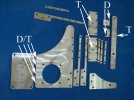
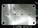
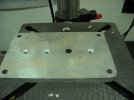
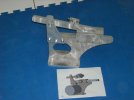
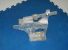
Photo 1 is of all parts, I labeled the parts that needed to be tapped with a T.
I also labeled the parts that needed to be drilled with a D.
And you guessed it if it needed to be drilled and tapped it was labeled with a D/T.
Photo 1 SHows what parts need what work.
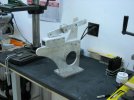
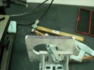
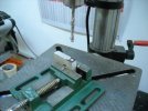
Photo 2 Main plate attached to a angle plate so it can be drilled to attach to the base.
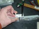
Photo 3 scribing centerline of the 1/2 plate
Photo 4 base temporarily placed on main body plate so I can transfer punch for location of drilled holes.
Photo 5 Transfer punched main plate ready for drilling
Photo 1 is of all parts, I labeled the parts that needed to be tapped with a T.
I also labeled the parts that needed to be drilled with a D.
And you guessed it if it needed to be drilled and tapped it was labeled with a D/T.
Photo 1 SHows what parts need what work.
Photo 2 Main plate attached to a angle plate so it can be drilled to attach to the base.
Photo 3 scribing centerline of the 1/2 plate
Photo 4 base temporarily placed on main body plate so I can transfer punch for location of drilled holes.
Photo 5 Transfer punched main plate ready for drilling
Attachments
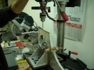
Drilling the upright
Tapping the upright
Countersinking the base
Lastly attaching the two parts with 1/4 x 20 flat head bolts.
Woohoo the hardest part is now done.
Maybe more tomorrow.
Chris
Tapping the upright
Countersinking the base
Lastly attaching the two parts with 1/4 x 20 flat head bolts.
Woohoo the hardest part is now done.
Maybe more tomorrow.
Chris
Attachments
- Joined
- Jul 14, 2004
- Messages
- 2,623
Thats great!!! whend she going into production??
Still working the bugs out of the cad files. I found two small issues with the parts when I had them cut. Already fixed those issues and another knifemaker who is also making one of these has offered a suggestion that I implemented for future renditions. Overall I think this could be a really nice DIY grinder as long as you do not mind drilling and tapping a few holes. While I do not intend to offer this for sale I do intend to put the Blueprints and DXF files on my website. Hopefully someone else can step in and offer a DIY kit. Me posting the plans will prohibit someone from charging too much or ripping anyone off with this design again I hope.
Well let the build continue.
Well let the build continue.
These next two holes I tapped at 1/4 x 20 but am thinking now I should open up the hole for the tooling arm lock to 3/8 x 16 which will mean tweaking the cad files for a larger hole.
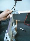
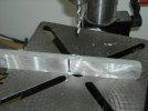
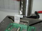
Next photo was where I transfer punched the upper pivoting arm for the part that holds the upper idler/tracking wheel. Two holes must be drilled and then tapped for 1/4 x 20.
Next photo was where I transfer punched the upper pivoting arm for the part that holds the upper idler/tracking wheel. Two holes must be drilled and then tapped for 1/4 x 20.
Attachments
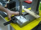
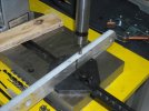
Next is drilling the two parts that hold the tracking wheel, drilling a 1/4 hole.
In the first photo I actually started to drill the hole in the wrong end and caught myself before I got very deep and put the hole in the right place.
Last part was to tap the plate that holds the tracking wheel 1/2 x 13 for the bolt that will hold the tracking wheel.
Next I just finished slamming the rest of the parts together.
Attachments
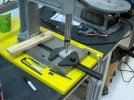
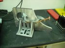
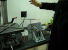
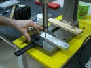
Last two photos is what she looked like after about two hours of work.
Next week I will bolt a tracking wheel, motor, drive wheel and tooling arm to her to see how she grinds.
If she works out as I hope she does hopefully you guys can start to get quotes in a week or so.
Chris
Next week I will bolt a tracking wheel, motor, drive wheel and tooling arm to her to see how she grinds.
If she works out as I hope she does hopefully you guys can start to get quotes in a week or so.
Chris
Attachments
Welding the base would work no problem.
I made my grinder out of Aluminum though and do not have the proper welder to weld Aluminum.
Plus having a background of being a machinist I tend to favor mechanical fasteners over welding, easier to modify or change my design when i can unbolt it.
IF one were to make this in steel welding would save a lot of time I believe.
Chris
- Joined
- Aug 1, 2008
- Messages
- 1,762
Chris,
Is there any reason not to extend the base out under the motor and adujust the spacing for the mounting hole in the main frame so that a c face motor with a frame mount on it could be bolted to the base and the frame? It seems that it would make for a sturdier steup to me.
Is there any reason not to extend the base out under the motor and adujust the spacing for the mounting hole in the main frame so that a c face motor with a frame mount on it could be bolted to the base and the frame? It seems that it would make for a sturdier steup to me.
Chris, if you could put the dimensions of each part in the parts picture, it would make it easier for the rest of us to build the grinder.
I don't need a cad drawing, I just need to know how big to make everything.
Thanks for everything you've done on this project!!!
I don't need a cad drawing, I just need to know how big to make everything.
Thanks for everything you've done on this project!!!
- Joined
- Dec 2, 1999
- Messages
- 9,910
Its looking good Chris. I think Bill is right about the base should be big enough to mount the motor on both ends. I would be willing to purchase the plans if you get to that point. Actually I want to make a scaled down version for smaller knives believe it or not. I have big grinders, I want a top quality small grinder.
I too have to commend you guys on pulling together. I read this entire thread and am impressed with you fine makers.
I too have to commend you guys on pulling together. I read this entire thread and am impressed with you fine makers.
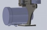
I know it appears that as soon as one would mount a motor the sander would topple over. This was by design so that as little material was needed to build this grinder as possible, Which makes it cheaper to have cut.
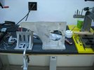
I should have included a photo of how I plan to keep this thing from falling over. But doing another plate that is wider is easy to do and I will have that as part of the plans also.
Photo attached.
I will post some blueprints tonight for those who want to hand build this or to scale it down. I probably will not post DXF files though until I verify everything works as i hope it will.
PS Bruce I appreciate the offer for paying for plans but figure nothing but bad kharma would come to me to accept money for this design after how this thread started.
I am officially calling this the EERF grinder, or Free spelled backwards.
Chris
PS The leveling feet are threaded and the plate that they go through is threaded, the extra nut is a lock nut to keep it all tight.
Attachments
- Joined
- Dec 2, 1999
- Messages
- 9,910
I know it appears that as soon as one would mount a motor the sander would topple over. This was by design so that as little material was needed to build this grinder as possible, Which makes it cheaper to have cut.
I should have included a photo of how I plan to keep this thing from falling over. But doing another plate that is wider is easy to do and I will have that as part of the plans also.
Photo attached.
I will post some blueprints tonight for those who want to hand build this or to scale it down. I probably will not post DXF files though until I verify everything works as i hope it will.
PS Bruce I appreciate the offer for paying for plans but figure nothing but bad kharma would come to me to accept money for this design after how this thread started.
I am officially calling this the EERF grinder, or Free spelled backwards.
Chris
PS The leveling feet are threaded and the plate that they go through is threaded, the extra nut is a lock nut to keep it all tight.
I can see what you mean about charging for the plans, all the better for me.

The feet on the motor base is a good thing and easy (cheaper) too.
How hard would it be to have a scaled down version for an optional size. As far as belts go I like the 1" x 42" as they are available in most all grits except maybe the higher ones over 600 plus they are cheap. I enjoy grinding on a 1" wide wheel for small work especially. The wheels would cost less too.