-
All For Sale threads must have a pic showing the knife being sold with written date listed, your username & Bladeforums or BFC to prevent photo harvesting from elsewhere - scammers hate this one trick! The rules for The Exchange can be found here. Please read and follow them. Stop using Paypal Friends & Family and follow our best practices to prevent getting ripped off or having a bad deal.
-
The BladeForums.com 2024 Traditional Knife is available! Price is $250 ea (shipped within CONUS).
Order here: https://www.bladeforums.com/help/2024-traditional/
- The Knife Exchange
- KnifeMaker's Market: Knives & More for Sale
- For Sale: Knifemaking Supplies & Tools
You are using an out of date browser. It may not display this or other websites correctly.
You should upgrade or use an alternative browser.
You should upgrade or use an alternative browser.
2" x 72" Belt Grinder kit $369.99
- Thread starter wilhurley
- Start date
- Joined
- Mar 19, 2002
- Messages
- 7,265
There is nothing wrong with the open source drawings. I have built my own KMG from them and appreciate the effort put forth for those of us that have used them for our clones. I do not believe that it is a bad thing to have more than 1-2 designs to choose from.
My own .02 anyway..
My own .02 anyway..
- Joined
- Jun 8, 2009
- Messages
- 97
Porter
Can you do me a favor and tell me whether or not your motor is a face mount type. If it is let me know the spacing between the bolts. I would like to make this for a face type motor and need to know if yours is the same as mine.
Chris
5 and 7/8 inches is the bolt circle diameter with the bolt holes starting at 45 degrees from 12 o'clock and then 3 more at 90 dgress apart. All 56 frame C face motors have this pattern
Porter
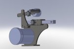
Thanks thats just what I needed, here is how it looks now. I have changed it up quite a bit but she is pretty close now to being finished. I actually plan to not put the bottom plate on now and just use the feet on my motor bolted to my workbench. I think it should work, we will see.
Hopfully get these parts lasered late this week or next week and assemble within a day or so. Should go together quickly, I figure this should only be a half a day project or so once all parts are in hand.
Chris
Attachments
- Joined
- Jul 13, 2009
- Messages
- 21,855
I plan to now use a 56c face mounted motor exclusively.
Chris
PS If your with me say Aye
Aye
I like the idea of 56C facemount with VFD and eliminating the pullies.
The Baldor motor site is a great resource.
Although you likely have all the measurements you need, I thought I would put this here for everyone else. Sometimes it's nice to see a drawing.
56C motor mount drawing specs.
http://www.baldor.com/DMS/documents/35LYT942.pdf?url=http%253a%252f%252fdmshq02%253a1095%252f%252fCache%252fCSProxyCache.dll%253fget%2526forward%253dhqdms%25253A1090%25252FContentServer%25252FContentServer.dll%25253F%2526pVersion%253d0046%2526contRep%253dZMARKETING%2526docId%253d459AE53ABFF901A7E10000002047AF91%2526compId%253d35LYT942.pdf
- Joined
- Dec 3, 1999
- Messages
- 9,437
Are you talking about carrying the entire weight and vibration of the machine with just a motor mount plate?
If that's the case, then it will not be rigid enough.
I might just be misinterpreting this though")
If that's the case, then it will not be rigid enough.
I might just be misinterpreting this though
Am I reading the images correctly that everything is cut out of .5" steel plate?
using 1.5" tool arms?
it looks like a very simple grinder and if measure plans become available, I'd certainly be interested in gettng them.
would having these water cut be acceptable? I know that at a certain point water cutting tends to get less smooth, but I don't recall what thickness that is. based on the parts it really seems like it would be possible to use a section of plate very efficiently with this design, with the appropraite placement of the individual parts on the cutting system
- Joined
- Sep 13, 2004
- Messages
- 1,553
Are you talking about carrying the entire weight and vibration of the machine with just a motor mount plate?
If that's the case, then it will not be rigid enough.
I might just be misinterpreting this though
Mr Wheeler is correct.
Also, not all c-face motors have a base so your limiting motor choices by not having a base incorporated into the grinder.
Well at least we are talking now, I am not married to any one idea and am flexible on this design. This is afterall our design, I am merely the draftsman.
So having said that 12345, the link is perfect and very helpful. Thanks I will put the motor foot on the drawing tonight and ensure my hole spacing is correct.
Therron258, While I did come up with an option to do the three step pulleys it is not something I am proud enough of yet to post. I also am wondering if just making it exclusively a face mounted grinder might not be the smartest way. One can after all just buy a 110v face mount motor, only downside is it is just one speed (But so is my bader b3).
Nickwheeler, while logic and common sense would say you are correct my bader b3 says something different. It has the casting mounted to the face of the motor and the motor is bolted down to a plate. Which is what gave me the idea. For those who opt not to bolt down by the motor, the bottom plate will still be part of the design. I am just opting not to use it. If one opted to use it they would just get the motor without the feet or have the feet facing the rear of the machine and use the grinders bottom plate.
Kindyr Yes this design would lend itself to either water jet cutting or laser cutting. You will get some slight draft with water jet cutting but it would not be bad I dont beleive.
Keep the ideas coming, I will post updated drawings later tonight.
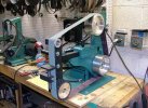
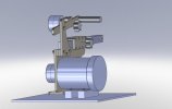
Photo of Bader below to show what I was referencing earlier, I lifted photo off of Google.
PS You will notice the small bar of steel off of the bader casting to the floorplate, I believe that is to negate the grinder from rocking or dipping on startup stressing the motor face.
So having said that 12345, the link is perfect and very helpful. Thanks I will put the motor foot on the drawing tonight and ensure my hole spacing is correct.
Therron258, While I did come up with an option to do the three step pulleys it is not something I am proud enough of yet to post. I also am wondering if just making it exclusively a face mounted grinder might not be the smartest way. One can after all just buy a 110v face mount motor, only downside is it is just one speed (But so is my bader b3).
Nickwheeler, while logic and common sense would say you are correct my bader b3 says something different. It has the casting mounted to the face of the motor and the motor is bolted down to a plate. Which is what gave me the idea. For those who opt not to bolt down by the motor, the bottom plate will still be part of the design. I am just opting not to use it. If one opted to use it they would just get the motor without the feet or have the feet facing the rear of the machine and use the grinders bottom plate.
Kindyr Yes this design would lend itself to either water jet cutting or laser cutting. You will get some slight draft with water jet cutting but it would not be bad I dont beleive.
Keep the ideas coming, I will post updated drawings later tonight.
Photo of Bader below to show what I was referencing earlier, I lifted photo off of Google.
PS You will notice the small bar of steel off of the bader casting to the floorplate, I believe that is to negate the grinder from rocking or dipping on startup stressing the motor face.
Attachments
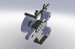
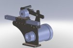
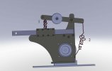
Alright here is where we are at right now. While the bottom plate is on this photo you can see it will not be doing anything and when I have my parts cut I plan to omit creating this part. I am mostly doing this in an attempt to make this grinder as lean and mean as is possible, er I mean cheap.
I will have the bottom plate as part of this package though, the individual can decide whether or not they choose to use it.
Hopefully when I put this together I can relate whether or not this was a good or bad idea.
Ok look at the sideshot, I recently made the upper arm longer than it was in the beginning so that one could either put a 3 inch coil spring between the tooling arm box and upper arm(Like a KMG)(option1). Or one could put a spring like the one on your screened in door at the end of the upper arm to the body of the grinder(Option 2). Tell me what you guys are thinking, I dont like the idea of the long rear spring because it would prohibit the tooling arm going to far to the rear, but maybe leaving the option viable is a good choice.
Keep the ideas flowing, I only want to have to cut this thing once to call it done.
Chris
Attachments

- Joined
- Dec 3, 1999
- Messages
- 9,437
If you have the motor bolted onto a designated steel plate with the support leg like the BIII then I think it will be just fine.
If it's screwed down to a 2X4 off the end of somebody's wooden bench (like you know most folks will do) without any kind of extra support leg, then this just seems like an awful big load on a motor mount without the rigidity to make it run optimally... But maybe not.
It's cool to see you guys pulling together after seeing the thread go downhill so bad.
forgive the dumb question....
my motor didn't come with the base plate it was supposed to. but it does have threaded holes on the face. is this motor going to work or am i going to need to a base plate or something to help support the motor?
my confusion comes from the recent posts.
again forgive my ignorance!
Jake
my motor didn't come with the base plate it was supposed to. but it does have threaded holes on the face. is this motor going to work or am i going to need to a base plate or something to help support the motor?
my confusion comes from the recent posts.
again forgive my ignorance!
Jake
No a face mount motor with no base plate will work fine. You will just have to have the bottom plate cut and use it to mount the grinder to your workbench.
I am attempting to not cut one part in an attempt to save money, IE THe big plate in the last set of photos is wood.
Chris
I am attempting to not cut one part in an attempt to save money, IE THe big plate in the last set of photos is wood.
Chris
- Joined
- Jul 13, 2009
- Messages
- 21,855
Ok look at the sideshot, I recently made the upper arm longer than it was in the beginning so that one could either put a 3 inch coil spring between the tooling arm box and upper arm(Like a KMG)(option1).
That's a Compression Spring
Or one could put a spring like the one on your screened in door at the end of the upper arm to the body of the grinder(Option 2).
That's an Extension Spring
Tell me what you guys are thinking, I dont like the idea of the long rear spring because it would prohibit the tooling arm going to far to the rear, but maybe leaving the option viable is a good choice.
In keeping the greatest flexibility of design, I say leave the arm long for both options.
The end user can see the possibilities of both designs and choose for themselves based upon the supplies they have available to them.
If they find that it is too long, they can always hacksaw it off pretty easily.
Seeing Adam-Micheal name here makes me think MAP ARM !
http://www.bladeforums.com/forums/showthread.php?t=466024
As I look at this design, I have pictured doubling up on the parts that create the tooling arm receiver tube to create a second parallel tooling arm to the left of the origional.
On the MAP ARM, how far apart do these two channels have to be?

Last edited:
so if i have this right. i will have to do the big steel base plate because i dont have a bracket to secure the motor to a wooden base or bench. and because of the torq an d weight etc. the steel base plate will keep it up right?
again sorry if this is just too dumb
jake
again sorry if this is just too dumb
jake