"Living With a Little Giant" The rebuild and continued maintenance of my 50lb hammer.

I am so
greenwnvy.gif
of everyone that has a power hammer, but I don't even have a forge built yet so I guess if I got one it would be putting the cart before the horse:o
 
Describe, or show a picture of what you need bored out. I can more than likely do the work for you for whatever the cost of shipping would be for you. I am enjoying this thread and don't want to see your progress come to a stop so if I can help I will.
Besides I may need to pick your brain in the future when I start my own rebuild.
 
Thanks Frank. I'm getting those wish list shop tools bit by bit. Damn wish list keeps getting bigger, somehow.

Brian, I appreciate the offer. I'll try to post some pics of what I'm talking about soon, you can see what you think. It should be pretty straightforward, drilling through a rectangular block off center (which I can do) and using a boring bar to get a sliding fit for a shaft through. Shaft is 1" cold rolled round steel. Block is 1-1/2" square mild steel.

I put a bit more work into it tonight. I've got the ram sliding much more freely with the front guide bolted on tight- I had to remove a spacer washer from the crankshaft in between the front face of the front bearing and back of the crankplate, and move it to the back of the front bearing, in front of the spider. This moved the crankplate back about 1/8". I removed some play from the right toggle arm/crosshead joint by adding a washer between the arm and the inside of the crosshead ear.
IMG_7508-1.JPG


This being on the front side of the arm, it also helped to push the arm back about 1/8" back toward the frame v-slide. So, I removed about half of the 1/2" gap between the ram when hanging free, and the back v-slide.

I also added another thin shim between the front guide and the frame on each side. The result is that the ram slides freely with much less play, with the guide bolts tightened. No more sticking. The shims are necessitated partly by the fact that a previous owner welded steel angle iron to the inside of the front v-guide.
IMG_7511-1.JPG


Since the ram is sliding well now, the clutch decides to stick engaged. So now, I'm thinking about trying removing a little height from the clutch blocks by removing shims. I'll post how that goes.
 
Last edited:
I've got it running pretty well now. Since I have it running off of a VFD, I've been able to trial run it while adjusting things, at half speed or so. Now, I'm running the VFD at 60 Hz and the hammer is working smoothly.

I'll write some text here about what all I've done since the other day. Tomorrow I'll try to go take some pics and insert them into this post where appropriate.

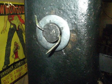
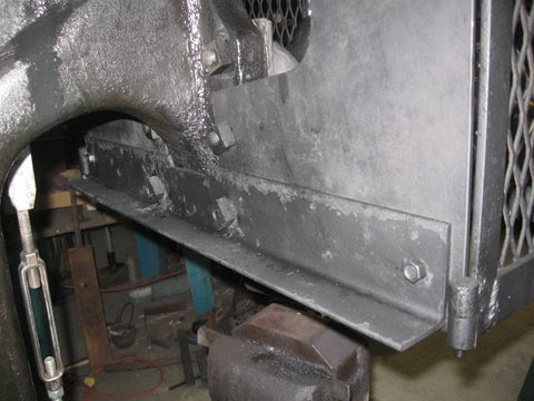
First off, the hammer would skid itself around a bit when running. Since I rent this shop and don't want to have to cut a hole in the floor and pour a hammer foundation, the wooden pad will have to do. To improve this, I drilled holes in the slab for 1/2" drop-in anchor bolts, then bolted angle iron stops along the sides and front of the hammer pad to contain the hammer pad from walking. The angles are only bolted to the floor, not to the wood. I figure if they are connected to the hammer as well, they'll probably tear up the slab at the bolt holes.
IMG_7517-1.JPG


This worked well, so far. The hammer is now stable when running, and doesn't rock side to side much, either.

I had been having a problem with the clutch failing to disengage fully. I unbolted the clutch blocks and removed shims one by one, checking for improvement each time by running the hammer. I removed a lot of shims and it didn't fully fix the problem.

So, I figured the clutch pulley was riding too tight on the crankshaft. There is a grease zerk on the inside of the pulley, for the clutch babbitt bearing. I greased the heck out of the bearing, spun it by hand, greased it more, ran the pulley at an idle, greased it some more, idled it more. After a while, the pulley spun on the shaft with much less grab. At this point, the clutch began to disengage fine. I ended up putting a couple of shims back under the clutch blocks when finished. I may put one more back tomorrow, as the tread ring bottoms out slightly when fully engaged. (Edit- I did put one more back. It works well now.)
IMG_7518-1.JPG


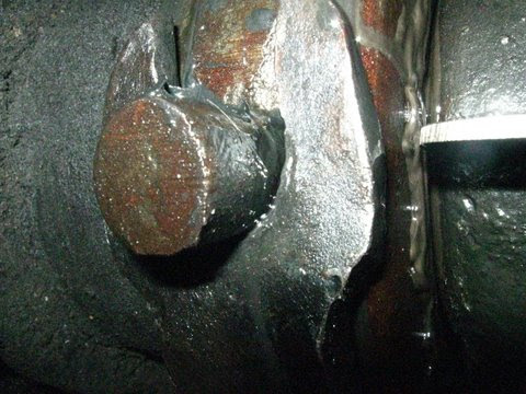
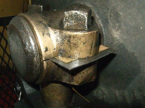
While working on this, I noticed that the shift fork was badly shaped. Some one had weld repaired it crudely in the past, failing to bend/align it correctly afterward. I took it off again and re-welded it more strongly, then hammered it and checked it until it fit more correctly.
IMG_7509-1.JPG


At this point, it fit well, but no longer lined up right with the pivot pin hole. I used the oxyace torch to cut the bottom of the fork out about 1/4" deeper on both sides, and filed it back smooth. Now it fit up and the pivot pin went through smoothly.
IMG_7510-1.JPG


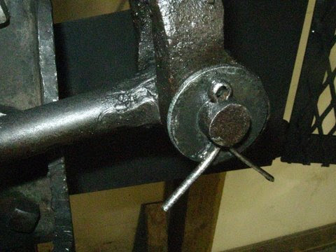
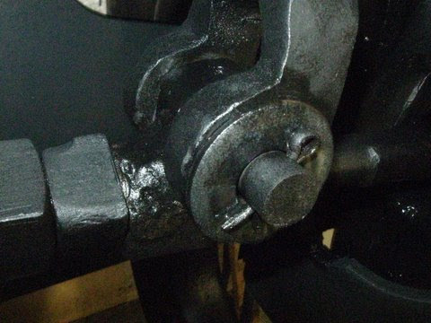
I also added a new washer to the cotter side of the pin here.
IMG_7515-1.JPG


I added washers to the front of the toggle arm/link joints to remove some play.
IMG_7506-1.JPG


IMG_7507-1.JPG


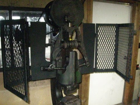
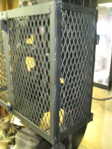
Points left to improve: Tomorrow I'll regrind the top die a bit, it's too aggressive a drawing shape. (Edit: Did that. Much better now.) I'll put a shim back under the clutch block. (Check.) I'll shorten the clutch link rod a bit- no problem with the turnbuckle welded into it. (Check.) And ultimately, I'll finish building my new double-adjustable toggle links and install them. (Soon.) These old beat-up ones actually work OK for now, though. And, I'll build the safety cage around the linkage. (Done. See below.) Oh, and re-bore the pin holes in the toggle arms, then turn oversize pins for them; the holes are worn significantly oblong with use. I'll still post when I do anything major to this beast on the future.

My wife took a short vid of me drawing out some stock on it. I'll post it too.

I'm putting this sucker to work now, got a lot of stuff to pound out for a fair over here next weekend!
 
Last edited:
Heck Sam, after I heard of this thing being for sale for the first time, I didn't have a choice about rebuilding it. It was meant to happen. I worked on it a lot when I should have been making knives...
 
Several points of interest that you might not know. The clutch fork and arms are case steel. I noticed you said you cut the hole out bigger on the pivot point of the clutch fork. You could have welded the original hole closed and drilled a new hole. During the rebuild course this is what we do. You can do the same with the arms if the pivots are to out of round.

If your ram guide continues to stick at the top take an extremely large bolt grind a ninety degree angle on it to fit in the vee way on the ram guide then take the bolt and another piece of flat steel against the frame and push the ram guide out at the top. Oh your ram guide must be bolted down tight. This will actually bend the top out slightly. Hope that made sense.

Good to hear your getting the ole boy running.

Dave from Diller
 
That does make sense Dave, thanks for the pointers. What I did was cut the ears a little deeper on both sides of the clutch fork- not cut the pivot hole bigger. I may try that trick with the bolt, though.

I ran it for a couple hours today drawing stock out. One of the shims flew out of the side of the crankbox- I'd not bolted it up tightly enough. After snugging it back hard, it was too tight on the crank and caused the hammer to run FUNNY. So, I added a .010" shim to each side. After that, it works great.
IMG_7504-1.JPG
 
Last edited:
Sorry, boys. I'll take the laptop next time I go to town and upload some video.

I built a safety cage around the linkage today. I found a nifty grate of expanded metal in an outbuilding here (another legacy of previous tenants) that turned out to be perfect. My other materials were 5/8” and 1” round stock, ¼” and 5/16” pin stock, some 1/4”x 1-½” flat stock, some angle iron, and some steel curb forms I had as scrap. All welding on this project was done at 125 amps AC with 1/8” 6011 rod.


I didn’t have any hinges, I live far from the hardware store, hinges are expensive, and generally under built anyway. So, I made my own hinge/knuckles by center drilling pieces of round stock, then sawing in half. I used 5/8” round with a ¼” hole for ¼” pins for all the corner hinges. I cold hammered a rivet head on the top of the pin.
IMG_7488-1.JPG


I did the same thing, but with 1” stock and 5/16” pins for the shackles (?) in the front. They lock up nice and tight, but easy.
IMG_7495-1.JPG


IMG_7496-1.JPG


The curb forms were 3/16” thick by odd-shaped. They form the sheet steel pieces on the back sides of the cage. They only needed a little trimming to be just right. I ran the hammer after installing the cage, and the cage flopped around too much; the sheet steel in the back was a little too thin to support the weight of the cage solidly with the slight rocking of the hammer. So, I added a piece of angle iron in the back to connect them. I wanted to weld it but went with bolts, to make it easy to remove. It solved the problem.
IMG_7482-1.JPG


I made it 22” high, 10” deep, and 28” wide. It clears the front of the guide by about an inch, and the adjustable toggle link end (two in the future) by about three inches.
IMG_7498-1.JPG


It swings out really well to afford access for maintenance and oiling. I gave it a coat of rattlecan rustoleum black to pretty it up a bit.
IMG_7501-1.JPG


IMG_7502-1.JPG


Cage walk around pics
IMG_7484-1.JPG


IMG_7492-1.JPG


IMG_7489-1.JPG


IMG_7500-1.JPG

This job took me nearly all bloody day. Whew.

By the way, here’s a piece of drawn out W2 next to the round stock I cut the “cookie” off of. It took me barely two heats to draw it out nice and clean. I’ve done this by hand several times, that takes many heats and MUCH effort. NO LONGER! I use a lot of 52100 bearings, too. The hammer makes short work of those as well. Now I have a big cable billet prepped and several cable billets and a Harley chain billet to finish.
IMG_7521-1.JPG
 
Salem, I see you suffered like we did for so long..Everything by hand.Big heavy slugs of HC steel by hand for hours before you even get to start making something :grumpy: Forging down 1"+ squares of high carbon steel is a humbling experience..:o
That #50 will do wonders for your regular blacksmithing too...
 
Big heavy slugs of HC steel by hand for hours before you even get to start making something :grumpy:

Exactly. And now when friends come by the shop I don't hand them a 10 lb. sledge.

Thanks Eric, Don. Don, I'll trade you straight across for your older LG 100#.:p Just think, your collection would be a complete with a 50. Oh, and a 250 and a 500.
 
OK. Here's a short hammer vid. Sorry, not much closeup or anything, and just some light drawing out. I've since built the cage and tuned it up a little more.

[video=youtube;k4cqlwVNexA]http://www.youtube.com/watch?v=k4cqlwVNexA&feature=player_detailpage[/video]
 
Salem that is awesome. It always warms the heart to see a valuable piece of equipment from yesteryear reborn and used! The smiths that purchased this new and used would surely appreciate the time and effort put into it. Besides its a piece of history. Bully for you sir!
 
Back
Top