"Living With a Little Giant" The rebuild and continued maintenance of my 50lb hammer.

Thanks guys. I just need to get back into some heavy knifemaking and make this thing pay for itself!

Phil, I do have a smaller footpath... the small forge you see me use in the vid, and the welding forge next to it, both have back doors that I can re-stack differently. Just fired up as normal with the little forge for the quick vid.

I've started tearing my welding forge apart- I'm gonna build a new improved propane/waste oil welding forge with 14" pipe and a better/bigger burner. I'll probably do a WIP on that when I really get going on it.

Thanks for checking it out, everyone.
 
Salem,

Just watched the video. Awesome man, Now all you need to do is paint it purple.

Purple power hammers always run better yet!

Dave from Diller
 
Purple, huh? Maybe. I really think that I may paint it neon green. Seriously. Kind of a like a neon/bright grass green.

That might look good with purple trim or pinstriping...

I only wish I could get neon green paint with a hammered finish. That would be AWESOME.
 
I worked on my Little Giant today. Finally went ahead and fabricated a new set of adjustable toggle links and knuckles. The old links were comically worn out and broken/welded. Check 'em out.

IMG_9078.JPG


IMG_9079.JPG


IMG_9080.JPG


IMG_9081.JPG


IMG_9082.JPG


I'm now able to preload the spring a little bit, taking the sag out of the links, (they should be about level at rest) and more evenly now that both sides adjust. There is less slop and mechanical noise, and the hit feels more solid.

I had a machinist friend turn class 2 threads, 1 inch NC, on some cold rolled round stock. I measured a threaded piece for length on the adjustable side of the old link, then cut both new links to that length.

I took 2 pieces of 1" cold rolled round, 3" long each, clamped them into a squared t-joint with the well beveled ends of the links, and welded first a hot root pass, then chipped and brushed, welded more passes, until I had it built up fully all around. I then went to the belt grinder and removed any excess bulk of the top of the beads and at the sides, so the t-links would pivot freely in the ram. It's important to burn this joint together very well, for obvious reasons.

IMG_9075.JPG


The stock I used is a bit bigger than the old links, they seemed to be rough forged 3/4"-7/8" dia.

IMG_9083.JPG


I made new knuckles for the pivot points where pins connect the toggle arms to the links. I used 2 pieces of 1.5" hot rolled square stock, 3" long each. I used calipers to scribe centers for the link and the pin. Both were located 3/4 in from an end, and centered in the stock. Centered in the end I suppose. The pin hole is 3/4" diameter, and runs 90 degrees to the link hole, which is 1" diameter. The pics should help.

I don't have a metal lathe, and drilling the holes would have resulted in too sloppy a fit. So, I turned to the milling machine. I first predrilled the pin hole at 1/4" using a collet and twist drill, then stepped up to a 5/8" twist bit and collet, then finish bored with a 3/4" end mill. I used collets throughout to avoid clearance issues when changing the bits (round column mill/drill.) The 3/4 pin slid in nice, as it's about 10 thou undersize. I did the other knuckle pin hole the same way.

I used a similar progression for the 1" bores for the links. After the 3/4" mill I stepped up to a 1" end mill. The fit was still a bit tight, so I ran the mill side to side just a little four ways. That got me a nice clean sliding fit for the links.

I had to grind the insides of the toggle arm joints flat and true, they were both a little too tight for the 1.5" knuckles. They needed it anyway.

I then drilled an oil hole in the top of each knuckle, intersecting with the pin hole. Later I will tap these for grease zerks.

IMG_9076.JPG


IMG_9077.JPG


I used nylocks for style. So far they seem to hold position well, I can add jam nuts if necessary. These knuckles and links came from both Richard Kern's book, and a conversation with Sid Suedmeier.

I also flipped the toggle arms around, and welded up one of the spring centers to center the spring better. I've seen pics of a hammer where the crankplate was worn incredibly by the top toggle pins and even the spring rubbing it- bad news. I was able to adjust the linkage out away from the crankplate a little more, and get more snappy controllable action from the hammer. The top die had a little side kick to the end of its stroke before, now it does not. Big improvement.

IMG_9074.JPG
 
Oh, the new knuckles lowered the link clearance a bit, so I raised the crosshead/pitman adjustment until at the bottom of the stroke the dies are 1.5" apart when resting.
 
Salem,

Excellent job on the adjustable toggle links and knuckles. They look good.

Here's something of interest from your photo's. Your toggle arms were forged and someone added a welded in brace. You will notice the hammered surface. Early style 50's had forged arms. Your arms were beefed up to make them look like newer arms which are cast. You have the original arms. Little Giant made them this way for awhile, but this is a slick mod.

Okay, one thing that you might want to look at since your photo's and rebuilding skills are above par. We need to look at your ram. As noted in your photo's, your toggle links are worn. If you look at them the ends where they sit in the ram are worn and rounded. You need to check where these set in you ram. I can almost guarantee that your ram is worn the same way on the ears of your ram. I bet there is a lip on the inside of your ram (on the ears of the ram where the toggle links T set). With your new toggle links they might run on this lip and will cause excessive wear in this area. Two choices build this area up with weld or grind off with a burr.

Take a look at this. I've seen some extremely badly worn ears on the rams that have almost cut themselves through the ram. Caused by under lubrication or plugged lube holes.

Dave from Diller
 
Thanks Dave. It's true about the arms, they are reinforced- the ends are pretty hammered, though. I'd like to get new ones when I can. They did a good job off welding in the extra.

I did check on that. The ram itself is not as badly worn as I thought it might be when I checked it- there is a little lip on the inside, probably 3/16" or less max. The links are welded up in such a way that they don't ride on the lips badly, although they do a bit. Do you mean altering the link ends or the ram? Because welding or grinding inside the ram would be no walk in the park...

I do have an additional problem or two I'd like to solicit your advice on. I'll PM you and if it results in work to the hammer I'll post that here. Thanks again Dave.
 
Salem,

You want to work on the ram, do not modify the links. I'll go over welding first on the ram. If needed you widen the slots that the links slip into. With a stick welder you bend the tips of your welding rod to fit in. It's kind of time consuming and eats a lot of rod. Yours sounds like there is quite a bit of material and it is not eaten out very bad. All you need to do is find a carbide burr that will fit in the eyes. An air die grinder works well for this.

I hope this helps clear up the process alittle.

Dave from Diller
 
It does, Dave. Thanks. More updates:

Well, it's always something. After drawing out bearings yesterday, I noticed the hammer beginning to run funny again. So I shut the forge down and had a look.

When I got the hammer there was a little too much space between the back of the crankplate and the clutch spider- meaning that the shaft would have about 3/16" of end play in the front bearing. My first answer was to install a 2" x 1/8" split thrust washer in front of the spider to take the play out. Worked fine for a while.

What I found yesterday was that end play had dramatically increased, now exceeding probably 1/2". Not good. This meant that either the crankplate was coming off or the spider has slipped on the shaft toward the rear of the hammer.

Upon inspection today, it turned out to be the spider. The crankplate ain't going anywhere, it's ON there. took the front bearing cap off to look, the spider had obviously slid about 1/2" back into the clutch side.

So, I ran a prybar between the clutch pulley face and the side of the spider casting to hold the spider from moving, and slugged on the crankplate with my big deadblow. Bingo, the shaft slid into the spider a bit. I kept doing this until the end play was down to less than 1/8".

IMG_9088.JPG


I figured the key was probably at fault. I assumed that the key would correctly be driven in tighter from the front bearing side, so I took some punches and a hammer and got the key in a good 1/4" farther. I cleaned up the little burrs raised on the side of the keyway with a file so they wouldn't ding up the babbitt in use.

IMG_9089.JPG


Then it occurred to me to call Sid Suedmeier to see whether my assumption about the key was correct. He picked up the phone and proceeded to give me all kinds of good advice. It turned out I was right about the key, but he told me to look for something else that's a common problem with old #50's. I ran out and looked.

I hadn't even noticed, but I saw it immediately once he'd told me to look- a wear pattern from the back ear of the ram (the top of the male vee) hitting the bottom of the crankplate at the top of the stroke.

IMG_9090.JPG


IMG_9091.JPG


I ran and called Sid back to ask the best way to cut it, he said oxy ace would be fine so that's what I did.

I put a wet rag around the greasy frame etc., and torched off a good 3/4" of the top of the ear. I ground it down clean with the angle grinder.

IMG_9093.JPG


IMG_9094.JPG


Sid said a good way to check is to put tape on the crankplate or ram to see if it's still happening. I did, used the hammer for about an hour, and no marks on the tape!

IMG_9095.JPG


My theory is that I changed the geometry of the linkage a bit with the new parts and raising the crosshead, causing the ram to rise higher at the top of the stroke. It began seriously contacting the crankplate, which introduced impact into the drive shaft causing the spider to loosen more.

Before and after the trial run (forging a 9" chef blade out of bearing stock) during which the hammer ran better than it ever has, I checked the endplay with a little feeler of scrap micarta. It fit the gap just the same before and after- no discernable movement. So, it seems I got the key tight enough for now (Fingers crossed.)

IMG_9096.JPG


Another thing that I'm very happy about is that the nagging problem of run-on with this hammer has ceased. Basically, it wouldn't entirely stop slowly throwing the ram with a foot off the pedal. That gets OLD when trying to do anything with top or spring tooling.

When I put the front bearing back on, I cranked the bolts down tight. The fact that this created a little more drag on the shaft, coupled with the improvement in spider position, has caused the run-on to cease. It'll still hit a beat or two after letting off of the treadle, not bad.

Dave Sloan mentioned that cranking the cap bolts could help, too. Between him and Sid, and my own ponderous logic, this thing is a great tool in my shop now. Thanks guys.

One other thing is that I added one shim under a clutch block, and raised the treadle a bit. Now I get more full engagement and faster and harder blows. I had it slacked off a bit formerly to reduce run-on.
 
Last edited:
Update: three years later, I have had to do the above procedure once again, to reduce endplay in the shaft. At some point in the future I may take it all apart and put a new key in there; we'll see how long this tightening lasts.

I took the top front bearing cap off to get at the key, and upon inspection, the babbitt in there looks like the day I poured it!
 
Hey Salem thanks for reviving this. I really wish BF was indexed in a way that made it easier to find gems like this... Until I read your thread today, I had trouble wrapping my head around how you poured the babbitt bearings.

I watched one of your forge press videos and in it I noticed you took the cage off of your power hammer. I was curious why? Did you use the radiator hose trick on the spring? Or did you feel it was unnecessary? I've read on IFI that the spring has exploded or shot out on occasion but wonder if I'm being too paranoid.

Thanks again!

-Clint
 
Clint! I'm sorry man, somehow I didn't see this. Hopefully you read it now. I took the cage off because years of incessant vibration cracked a couple welds on the hinges. I meant to repair it and put it back on, but darn it I just like the hammer better without it. I may put some heavy hose over the spring soonish- I have worked in shops where the hammer runs heavy for years with no guard at all on the spring. I think I'll be a bit more safety conscious than that!

Yesterday I took the top end of the hammer apart again. The spider had slipped on the shaft again, worse than ever. No clutch control at all.
I engine hoisted the shaft down, with the clutch pulley tied onto it so as not to fall off.
DSC01068.JPG

DSC01069.JPG

When I got it to the floor, I cribbed up around it until the crankplate was off the floor and the weight was supported by the crank side face of the spider, then started slugging down on the end of the shaft with a heavy dead blow hammer. I ran some PB Blaster down the keyway and around the shaft.
115h2ygNzPMotcJBAcpffwOhhRWW2VbTQwePB-HpGGE=w387-h516-no

After hammering on it quite a bit, and cribbing it up some more for clearance a couple of times, I got the spider off.
DSC01071.JPG

DSC01072.JPG

I called Roger Rice at Little Giant, and he recommended trying to shim the key up. A most helpful fellow!
I found that an old hacksaw blade, ground flat and dulled, was just the right width for the keyway, and .023" thick. Figured I'd try that.
DSC01073.JPG

I put the key back in, with about 3/4" of damaged end cut off and dressed, with the shim under it.
I padded the crankplate with a wood block against the floor, and slugged the spider on until it came flush to the shaft end. I grabbed a chunk of 2.5" pipe out of the scrap pile as an outside drift to beat the spider down around the crankshaft, and kept slugging it down with the deadblow.
DSC01074.JPG

I determined that just about exactly 6" was the correct space to leave for the front bearing, to minimize end play. I cut a 6" spacer stick from scrap steel to hold in the gap as I got close.
Near the end, I had to drive the key back into the spider a bit so it wouldn't contact the bearing- to finish seating the spider, I put a little steel spacer in the keyway end to keep the key back inside the spider. I pried it out when done.
DSC01075.JPG

The spider was seated quite firmly by the time I got it tight to the 6" spacer stick, which was promising.
I hoisted the assembly, clutch pulley tied on again, and fiddled around a bunch trying to get it onto the pedestals, almost dropping it on myself! It is difficult, as the obvious way of rigging the works is to tie or sling onto the shaft. That gets in the way of the bearing seating. I ended up tying to the clutch pulley on one side, and clamping a BIG c-clamp to the crankplate in the right spot and tying to that as well. That allowed me to keep my rigging out of the bearings, and get the shaft installed.
After wiping the bearings, shims and mating surfaces clean, then oiling the shaft and bearings, I put the caps and all the bolts back and snugged them.
I test drove it on a chunk of 2x4. I was able to feather the clutch well, and the hammer did not run on.
I'll be drawing out some pattern weld over the weekend, and will report should the re-key job not hold up.

Thanks for reading another installment of "Living with a Little Giant 50." Hopefully this helps someone.
 
Well, the damn spider key is slipping again. I am getting tired of this problem. I will call Little Giant this week for some advice- I think there may be a misalignment problem in the linkage that tends to pull the shaft back and forth during the stroke, leading to the endplay problem. I will post what I find.
 
Hey Salem I didn't realize you responded to my question. It's good timing though since I've finally setup my power hammer after it sat since I bought it in February...

I think I'm going to try and make something like a window similar to what I saw a guy on IFI do. I'm going to get some 1/4" lexan and make a small frame for it and bolt it to the crosshead. It should be light enough to not interfere and all I really want it to do is deflect the spring and any shrapnel away from me.

I'll post a picture once I finish it.

Sounds like that spider key has been a real pita. Good luck in fixing it, hopefully this one will be more permanat.

-Clint
 
Well... the spider key continues to be an issue. I have been looking at the linkage and alignment of parts to try to suss out where forward pulling forces on the crankshaft may be occurring during the stroke. A theory I had was that the babbit had been poured slightly out of square with the ram v-ways. Upon inspection this time, I found that the precautions that I'd taken when pouring the bearings were adequate- it's pretty damn perpendicular to the ram slide surface on the hammer frame. Now I'm focused on some slant extant in the toggle arms.

I took the top end of the hammer apart again, put another shim in on top of the existing shim that I'd previously installed. I used some bandsaw blade this time, about .030" thick for a total of .053-55" of shim. I smacked the spider back into position on the crankshaft (very difficult).

Now, the clutch pulley is such a tight fit that it has to be slugged onto the spider with a deadblow! I have to take it back off. I'm pretty sure what happened is that I shimmed the spider key up far enough, and drove it on so tight, that the spider "shaft" that goes inside the clutch pulley is now slightly out of round, having been stretched oval a few thou. Damn!

I'm trying to come up with a solution right now... if I find that my assumption is indeed true, by measuring the spider shaft OD, then the only option I can see is to pull it back apart and lessen the amount of shim.
 
The life of a champion is never easy. ;) It's a testament to you that you are able fix old iron.
 
An update on the hammer...

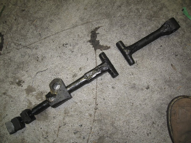
It broke the other day. One of my fabricated toggle links snapped right in the middle- parts flew past me and only bruised me on the knee. Close call.

vE90GjS.jpg


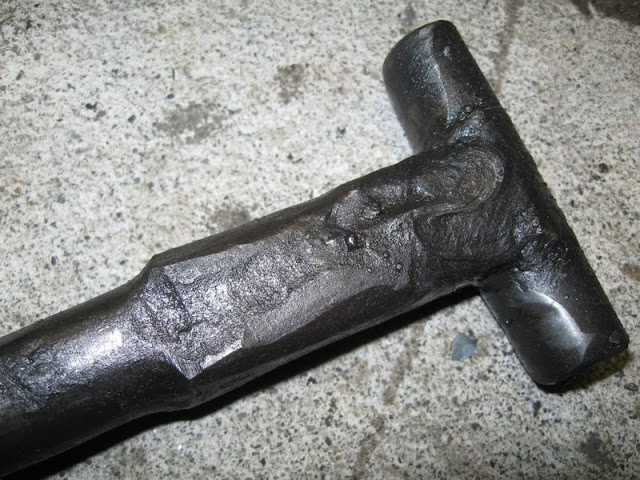
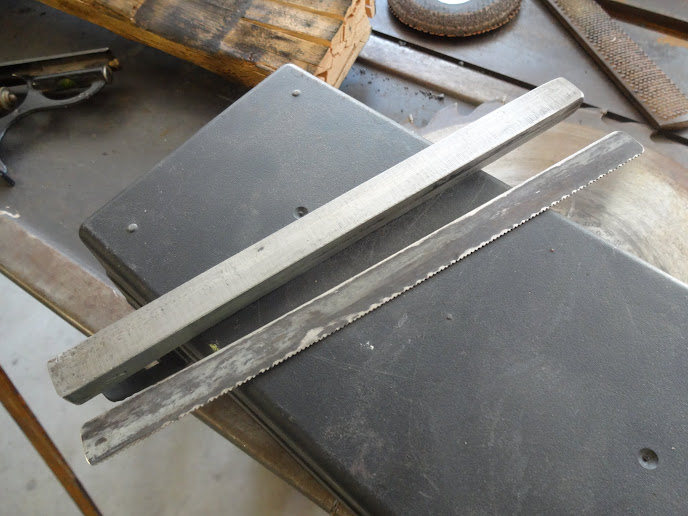
I threaded up a new link on the lathe, and welded the "T" up. It fit right back into the hammer.

GMXQZZQ.jpg


WunhJ4K.jpg


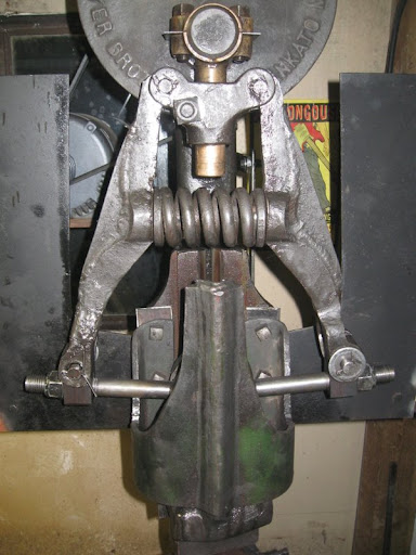
I fixed the safety cage and re-installed it. Safety up!

skIjIvi.jpg


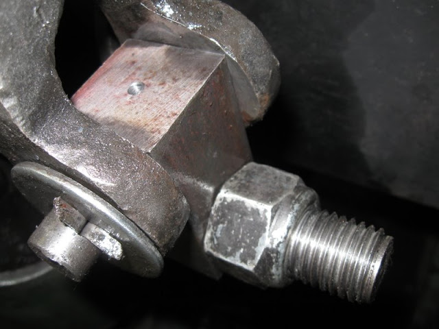
Prognosis: the link, unnoticed by me, and due to recurrent maladjustment caused by excessive shaft endplay, had begun to hit the ram guide, and metal fatigue combined with a stress riser from the end of the adjustment thread had caused it to snap!

I finally had absolutely enough of the clutch spider coming loose. After talking to Roger Rice at Little Giant (Sid retired) I settled on a course of action.
I could measure everything, and machine a new key to fit- or, just bypass the key problem entirely and pin the spider to the shaft.

Well, why not? Couldn't think of any good reason why the spider should be on there with a key, rather than pinned. The clutch blocks can be replaced with the spider bound to the shaft, and any other piece can be removed at will regardless of the position of the spider.

So, that's what I did. Here's some pics of the process.

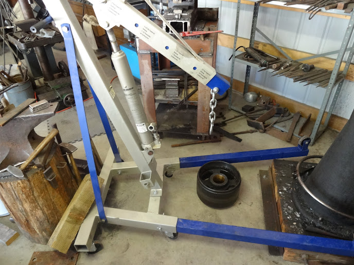
Hoisting the top end off. This is a badass engine hoist!

e6p09JD.jpg


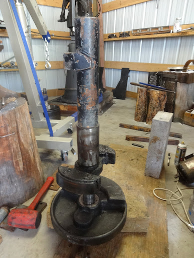
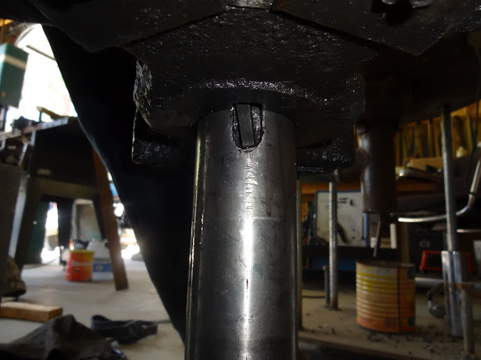
Used my lower squaring die from the forging press, as a V-block to set up the shaft assembly for drilling... then blasted away with centering bit, then a 3/8" twist drill. Good old 20" VS JET drill press got through spider/shaft/spider, no problem.

CMasBHk.jpg


I countersunk both sides of the through hole pretty heavily, to give room for a recessed rivet head.

QDDF6ve.jpg


I had some 3/8" round silicon bronze on hand, which I decided to use for the pin. It's almost as strong as mild steel, and would be a heck of a lot kinder to the clutch pulley's inner bronze bushing should the pin break at some point.

5XhwmEq.jpg


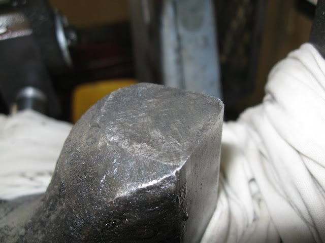
I heated up one end of the pin with an O/A torch until red, then with the other end backed up with a sledge hammer, beat a head onto the pin, upsetting it into the countersink. Then I did the other side of the pin the same way, finishing up by peening in farther with a ball peen.

m3GLfMv.jpg


After cleanup, side one- ground a little below spider surface to not contact clutch cone inner bearing.

j9QAatB.jpg


Side two, riveted and cleaned up.

heI3lgQ.jpg


Key driven to rear end of spider, and lightly tacked into keyway to immobilize. It's not serving its primary purpose anymore, so I don't want it sliding out into the babbitt area. I can break this free again, easily enough, if necessary.

3A39v5d.jpg


Installing top end back onto hammer. This clamp rig works well.

ZxY16Wm.jpg


It took some fitting at the end, grinding off some high spots from the front bearing face of the spider. It looks as if it cracked and was repaired in the distant past, and the two halves were not perfectly aligned when welded. With the spider pinned on precisely, it would bind to the front bearing pedestal a bit during rotation at the two weld points. I suspect the fwd/rev wobble to the shaft created by this geometry may have had something to do with the spider breaking free repeatedly. It's gone now.

I test drove the hammer. It hit hard and controllable- so far so good. I'm off to the shop after this post, to forge some damascus, and I'll report on how it does.

RHzp7Cs.jpg


I wanted to post all of this, as I've been unable to find anywhere else on the web where this has been done, documented, or even talked about.
 
Last edited:
You are correct, the thread served as a stress riser. That set of toggle links was machined for me by an acquaintance, and he did not end the thread in a smooth fashion. I threaded this one myself, having a lathe now, and made sure to run the minor diameter out past the end of the thread a little, then chamfer it up to the link surface.

The entire thread does not have a radius at the root. My 18" Hendey lathe has messed up halfnuts, so the little lathe was pressed to thread this 1" bar, and i was taking 1 thou per pass the last ten passes. It barely had the power! I don't think a cutter with a slightly round nose would have panned out well.
 
Back
Top