-
The BladeForums.com 2024 Traditional Knife is available! Price is $250 ea (shipped within CONUS).
Order here: https://www.bladeforums.com/help/2024-traditional/
You are using an out of date browser. It may not display this or other websites correctly.
You should upgrade or use an alternative browser.
You should upgrade or use an alternative browser.
Looking for Fairbanks hammer operating manual...
- Thread starter Mike Krall
- Start date
- Joined
- Nov 2, 2009
- Messages
- 162
Hey Guys! I maybe came up with a motor mount design that could work! I would mount the jackshaft up high on the right hand side, slightly below the bottom of the drive pulley height. It would be about exactly where it was, but the jackshaft would be turned 180 degrees with the drive belt pulley on the jackshaft in front and the motor belt pulley in the back. The motor belt pulley on the jackshaft would stick out past the back of the hammer enough for clearance (I will need to make a short jackshaft of around ten inches). I would mount the motor down on the back of the hammer up about the height of the top of the anvil or just below the hole through the frame (it would block the hole). The pulley on the motor would be in towards the frame of the hammer, so everything would be tucked in as close as possible (this pulley would be in line with the jackshaft pulley but at the center of the back of the frame and down lower).
This setup would result in a drive belt from the motor to the jackshaft of about 24-30 inches in length on a straight line or 48-60 inch loop. The weight of the motor would be down at the height of the top of the anvil, and the motor would be opposite the anvil on the long axis of the hammer, or front to back.
This design achieves several goals: 1) The hammer is as balanced as possible with the added motor weight being low and in line with the anvil weight and on the back of the hammer; 2) I am using a jackshaft for speed adjustment potential; 3) There is no extra steel framework around and over the machine - everything is self-contained on the hammer; and 4) The design only requires two basic mounts to be fabricated.
The treadle design may be an issue, but the drive belt and jackshaft belt orientation would be the same as when I bought the hammer. That setup looked pretty woeful and needed to be reworked, however. I am definitely going to need ideas on it.
I need your comments/criticism about this design before I take it any further. Oh, I almost forgot. Mike, my motor's pulley is 3 and 1/4 inches in diameter.
- Joined
- Feb 4, 2005
- Messages
- 834
Regarding an overhead mount. OK, now picture standing in a room with about an 11 foot ceiling with your hammer and build some type of steel arch or beam up beside or behind your hammer and stick the motor on top of it approximately 10 feet in the air (7 feet for hammer height and 3 feet for belt length). It would look more like some kind of monument to the motor gods than a motor mount! Something in the roof rafters looks OK, because all that you see is a belt coming down from the roof rafters. Fellas, I stood at the feet of the motor god monument, and I was in awe of the power of the mighty motor god, but I didn't like it as a hammer mount. Come on guys, we can figure something out!
Mike, I measured the flatness of the belt pulley with a set of calipers - completely flat for all I could tell.
I will measure the little motor pulley, but it is very small - as small as they could make it I believe. Mike, thanks for the explanation of the calculations for beats per minute. That is some real information that anyone who reads our little chat can use forever.
Bruce, I was looking at pictures of every hammer I could find on the internet last night. Some (all?) Little Giants had the motor hung off the side up top. I need to find a picture of a larger LG to look at. Somehow they stopped the wobble.
Mike, I am not quite getting your concern about the idler setup and the belt contact surface, but it seems like an important point. How should the idler be applying pressure to the belt to increase the contact with the drive pulley rather than decrease it? Just because a hammer can function with a messed up setup doesn't mean it is functioning as well as it was designed to do. The guy who sold my hammer to me said it was in good working order, but it had one pin broken completely into, all of the pin holes were worn out and way oversized, etc, etc. A hammer hitting is not necessarily a hammer hitting well.
One of the things about setting up in a chicken coop... lack of elegance does not drive design decisions... =]
The catalog pictures will show you how the tightener pulley, tightener pulley arm, treadle linkage, brake weight work. In all instances, depressing the treadle pulls on the short arm of the tightener pulley arm and the tightener pulley moves up. The normal belt position is just loose enough between drive pulley and driving pulley to keep the hammer from running on it's own and/or burning the belt. The tightener pulley moves the slack side of the belt towards the driving side of the belt and increases the amount of wrap the belt has around those two pulleys.
Dan's set up is a linkage rebuild and includes repositoning the brake weight. Treadle movement still pulls the short arm (I guess it could be pushed, with the right linkage design) but the upside down tighterner pulley arm moves the pulley out and tightens the belt by spreading the slack and drive sides of the belt. I believe, but don't know, it's the type of belt Dan uses that allows less pulley/belt contact area to pick the hammer up as easily as it sounds like it does. He could turn it back to normal but it would likely require a shorter belt... just long enough.
Bruce can tell you about the disadvantage of running a flanged pulley on the motor or driving end of a jackshaft.
It's a lot easier to mount a motor on an LG. There is no belt-as-clutch complication. The belt (either one flat or multiple "V's") run motor to drum and the clutch is a shoe system inside the drum and actuated by treadle/linkage. LG's also have a big flat (relative to size of hammer and motor size/hp required for it) just about exactly where a person would like one to be for a motor mount.
It surprizes the heck out of me the drive-end JS pulley isn't crowned... is your drive pulley crowned (doesn't show it in your pics, that I noticed)? Maybe the short distance helps.
Both Robert and Dan... standing at the back of your hammers, which way do they turn... CW or CCW? As far as I know, there is no reason they cannot turn either way but the tightener pulley and arm DO clutch on the slack side (normally, I guess I should say) so Fairbanks turn CW, as viewed from the back.
Mike
Last edited:
- Joined
- Feb 4, 2005
- Messages
- 834
I need your comments/criticism about this design before I take it any further. Oh, I almost forgot. Mike, my motor's pulley is 3 and 1/4 inches in diameter.
With the other pulley diameters and no system slip, it's a max bpm of 158... less with slip, of course.
Robert, I'd have to take measurements, do drawings, drink beer, sleep, drink coffee, think, then do more measurements and drawings to give you a yes or no. Given Dan's hammer's goat-screw of an actuation system and the one yours came with, anything can be made to work.
I'm a person who is going to start with "right", then stick with that until the impossibility of it beats me into other solutions. If you are convinced the belt can be tightened by widening as well as narrowing, the options increase. I don't believe the tightener pulley can do other than operate on the slack side of the belt. I know the drive belt pulleys have to be in the same plane. The two shafts need to be parallel... adjustable to that. The tighter the belt and the closer the tightener pulley is to the belt, at rest, the better. The larger the possible arc movement of the tightener pulley, the better. In the end, what is going to matter is all the stuff between the treadle and the linkage connection to the tightener pulley arm... including brake release movement and pulley arc. The motor/JS need to be set up to those realities.
In your present motor/JS senario, I'd have the motor on a stand below the JS long before I'd have it on the machine, especially blocking the hole long pieces have to go through to be hammered.
Two last things for the night...
Bruce has it right... Sid has more good understanding of "can and cannot" with hammers than any living human being by a distance so great, it approaches infinite. There isn't anything he can't answer quicker and better. You don't happen to be anywhere near eastern Nebraska, do you? Take your pictures and go visit.
Other thing is, how are you tying your hammer to your concrete floor?
Mike
Last edited:
- Joined
- Nov 2, 2009
- Messages
- 162
Hey Fellas. Mike, what would be the best part of my drive system to change in diameter to get to the correct bpm?
I was going to ask about blocking the frame hole. Working off to the side, is there really many times when you use the hole through the frame? I have 2 tapped 1/2 inch holes in the frame just below the frame hole, and there is a flat spot on the frame there, and that is why I was mounting exactly there.
I haven't yet decided on exactly how to tie the hammer to the floor. The hammer will be elevated on a platform that I have built that is about 5 and 1/2 inches high. I figured I would hammer drill the floor and place some bolts, but it was mentioned earlier basically trying to place nuts in the floor, so the machine can be slid rather than lifted over them. Seems like a great idea but will be a little trickier to do.
Mike, why do you say you would mount the motor on a stand below the jackshaft rather than on the hammer?
I will try to make a drawing of the mounting setup I am thinking about and scan it or something. Would be easier to discuss then.
The way my idler pulley was mounted before, it had to have a really long range of motion to lift the ball weight up to around vertical, so the pedal wasn't really hard to push, I guess. Therefore, the belt was really long to accommodate the long idler pulley travel. When you stepped on the pedal, the pulley lifted and lifted taking up a bunch of slack, until the weight got close to vertical where the weight lightened the tension for holding your foot on the pedal. All of that belt slack needs to be eliminated, so I need to change that setup.
- Joined
- Feb 4, 2005
- Messages
- 834
Hey Fellas. Mike, what would be the best part of my drive system to change in diameter to get to the correct bpm?
I was going to ask about blocking the frame hole. Working off to the side, is there really many times when you use the hole through the frame? I have 2 tapped 1/2 inch holes in the frame just below the frame hole, and there is a flat spot on the frame there, and that is why I was mounting exactly there.
I haven't yet decided on exactly how to tie the hammer to the floor. The hammer will be elevated on a platform that I have built that is about 5 and 1/2 inches high. I figured I would hammer drill the floor and place some bolts, but it was mentioned earlier basically trying to place nuts in the floor, so the machine can be slid rather than lifted over them. Seems like a great idea but will be a little trickier to do.
Mike, why do you say you would mount the motor on a stand below the jackshaft rather than on the hammer?
I will try to make a drawing of the mounting setup I am thinking about and scan it or something. Would be easier to discuss then.
The way my idler pulley was mounted before, it had to have a really long range of motion to lift the ball weight up to around vertical, so the pedal wasn't really hard to push, I guess. Therefore, the belt was really long to accommodate the long idler pulley travel. When you stepped on the pedal, the pulley lifted and lifted taking up a bunch of slack, until the weight got close to vertical where the weight lightened the tension for holding your foot on the pedal. All of that belt slack needs to be eliminated, so I need to change that setup.
If you switched out the JS to drive-pulley pulley with a 5" (non-flanged and crowned) the bpm would be 235 instead of the now, 158. I'd do that then get two, two sheave, "V" belt pulleys to run on motor and JS motor-end that made the spec 350 bpm... but that's me. At the least, do your JS thing so there aren't limitations on switching the "V" pulley(s) later.
There is data out there on drive belts... flat, "V", whatever... that I don't have in my head. Each of the types have pro's and con's. One aspect driving use of belt types is pulley sizes and distance apart... for a belt type, there are limits on how-close/how-far and that varies by pulley size relationship. The link I put up earlier in the thread has some info and links to other places for more detail. Searching "flat belts" or "flat belt pulley" might help.
This is the way I see the brake release, etc. There are tension springs on the treadle that need to shorten enough to lift the treadle as high as it will ever need to be lifted (maybe further than is appparent). They need to not load excessively when stretched and that is their only function. The brake weight and arm (on ours and Bruce's) adjust... the ball can be set anywhere on the arm. The arm can be set in a variety of positions and those positions vary in effort to move by easy at first/harder later to harder at first to easier later. That and the length between brake arm pivot and brake arm weight change how the hammer responds to braking and de-braking. I don't know what the function-type or range-of those changes are. All the pictures I've seen show the weight at the end of the brake arm. Many pictures show the brake arm horizontal when the brake is on... maximum leverage on brake cam... minimizing lifting effort as tightener pulley moves further through arc.
It seems like you should be able to position the JS far enough away from the drive pulley to fall between "go"/"no go" for flat belts and have the tightener pulley come up from underneath so the slack side is moved towards the drive side (normal). Doing this would have your hammer rotating CCW from the back... opposite of "normal" (might be a person could move all to the other side, in which case, rotation would be CW/"normal"... and/or be a better place for the mounting mods.) Anyhow... Given the length ratios of the tightener arm mechanism, there is not a lot of wiggle room... without fabricating a new tightener arm (could be done but changes will create implications), the length of the arc the tightener pulley can move is the defines the area your solution can be found in.
Given the JS can only be certain places in your now-design, there is an area underneath it that can't be entered with out watching out for the turning pulleys and belts. If there is a motor on a stand beneath the JS, you will never get into the JS inadvertently. It seems easy to me to have the motor set this way and build in a tightening mechanism for the motor-to-JS belts and I would use the frame for organizing other things and/or making other things handy to hand... the old "stuff has to be somewhere" line of thought.
One thing to note... "normal" has the tightener pulley contacting the slack side significantly closer to the drive pulley than to the motor/JS/driving pulley in all configurations. I can't articulate the reason for this, but I don't doubt it's a reason-for-function.
If I missed anything... holler...
Mike
Last edited:
- Joined
- Nov 2, 2009
- Messages
- 162
Happy Thanksgiving fellas.
Checked on Naval ships and Ol Bill said all the tenders he ever saw had extensive machine shops aboard. He was familiar with the destroyer tenders, AD designation, such as the Arcadia, Cascade, Yosemite and the Piermont. Also said the sub tenders had big shops. ANother comment he made was that the cruisers had big shops onboard. He was familiar with the Macon. Boy , did those names bring back memories of my dad's conversations with his fellow sailors of days in the Pacific!
So that might be a starting point to for a search of Naval archives for hammer info.
So that might be a starting point to for a search of Naval archives for hammer info.
- Joined
- Feb 4, 2005
- Messages
- 834
Good lick, Bruce...
Mike
Mike
- Joined
- Nov 2, 2009
- Messages
- 162
Hey Fellas. I've been busy building a welding table and a rolling cart for steel.
My side arms, links and cross head are getting shipped to Sid today. He is going to weld the holes shut in the side arms and links (or make new links if better or cheaper) and bore new holes and send me new soft pins that rotate freely and a new spring. Price seems reasonable, and I trust Sid. His estimate is $60-70 each for side arm work, $50-60 to bore the cross head to match side arm hole size, $80-110 for each link, $12-16 for each pin and $78 for a new spring.
I hope everyone had a good Thanksgiving. Bruce, are all of the turkeys still in the woods or did one end up on the table?
") Did try for a wild bird but they were just too elusive for me. We're now in the middle of deer season but no luck so far.
Did try for a wild bird but they were just too elusive for me. We're now in the middle of deer season but no luck so far.- Joined
- Feb 4, 2005
- Messages
- 834
I've barely been able to make time in a day to work on knives I'd have liked to have had done already. Got snow and cold this past three days and didn't feel like jump shooting ducks in 10F - 20F weather so a person would have thought knife making would have time. Got paper work instead... =[
You are in good hands with Sid and Keri, Robert. By the time you are done with this, you are going to have made friends for life... they are those kind of folks.
I'm hoping Ron_m80, from back in the beginning pages of this picks up on the boat names and finds and interest in knocking around Navy Archives. He seemed like he has a bent for that kind of thing. I'll mess with it if I have to but it will be like pulling teeth if it's anything like other Government archive stuff I've had to mess around in.
Mike
- Joined
- Nov 2, 2009
- Messages
- 162
Bruce, do you make dies? "Tripp" on Iforge in the hammer forum is asking for some for a Fairbanks E model. For some reason, I am thinking you have made some.
My parts are off to Sid, and I need to get the hammer frame to a machine shop this week. Going to be a little quiet for a little while. Although, I am thinking of a trip to the university library to see if I can dig up some info on our hammers.
My parts are off to Sid, and I need to get the hammer frame to a machine shop this week. Going to be a little quiet for a little while. Although, I am thinking of a trip to the university library to see if I can dig up some info on our hammers.
- Joined
- Feb 4, 2005
- Messages
- 834
"Bear" makes his own dies but he has old ones to go by. He cuts them out on a bandsaw and a belt grinder. fits them with a 4 1/2" angle grinder. Most folks would need some machining to be done to have them be "real dies"... =] It's the specs a person needs, really. Some of the numbers can be gotten from inference. Like the size of the dies is the size of the hammer face. Depth of the male dovetails is 0.025" less than the depth of the female dovetail (on a 50#, at least). Height dimensions are tougher but I suppose they might be proprotional so a person could figure height on an "E" from height on an "A"... same with die keys, probably, and that would give a person a decent number for male dove tail width from female dovetail width. If it was me and I was looking to get some made, I'd call Sid and ask if he thought he could come up with the numbers to do it... or... get Sid to connect a person up with Doug Freund who might have numbers.
Mike
Mike
- Joined
- Nov 2, 2009
- Messages
- 162
Mike, you always have the technical info. Thanks for the response Bruce. I must have thought you made them from what you had for sale. I am going to have to get a set made as well. I got 5 sets with the hammer, but they were all worn out! What specific shape would you guys recommend for general shaping work on lamps, furniture, etc.?
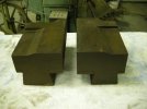
I'm really pleased with the set of combos that came with mine. One side is flat , the length of the die, front to back. The other side is of 2 different angles, one slight the other pretty steep for drawing. That make sense?
I been teaching myself how to form knife bevels on the shallow section. Only different design I would want would be the have the bevel shallow the whole length.
If that doesn't make sense, I'll post a picture.
I been teaching myself how to form knife bevels on the shallow section. Only different design I would want would be the have the bevel shallow the whole length.
If that doesn't make sense, I'll post a picture.
Last edited:
- Joined
- Nov 2, 2009
- Messages
- 162
Bruce, thanks for the picture. What is the point of them stepping down like that?
I took my shaft to a few machine shops today. One shop said the shaft might cost $500 to have one made and bushings and all might run $1,000 total. That made my throat dry. I got sent from here to there, and ended up at a shop where a guy rebuilds old machinery. His suggestion was to turn my shaft down to clean up the scouring where the bushings set on the shaft, and leave the rest of the shaft the way it is, so the crank and the drive pulley will ride on it unchanged. He will also make new bushings of bronze to match the new diameter. He was able to easily scratch the shaft with a file, so it is not hardened.
He told me that bronze bushings should be oiled instead of greased, so I should not convert to greasing the main bushings. I will ask him more about that.
I need to go back, because he wants me to pull the bushings and bring them back with the shaft, so he can determine better how much to take off the shaft. I guess the wear will be more apparent if he has the bushings as well. His suggestion for pulling the bushings was to use a piece of pipe larger that the bushing and some all-thread with a large enough washer to grab the bushing as the all-thread is tightened which would pull out the bushing. I think he has done this stuff before, looking at the old equipment he had around and what he was using.