-
The BladeForums.com 2024 Traditional Knife is available! Price is $250 ea (shipped within CONUS).
Order here: https://www.bladeforums.com/help/2024-traditional/
You are using an out of date browser. It may not display this or other websites correctly.
You should upgrade or use an alternative browser.
You should upgrade or use an alternative browser.
Optimal position of the liner lock
- Thread starter alan0354
- Start date
- Status
- Not open for further replies.
I don't care how easy to close the knife, I make all mine very easy to deploy, better than new when they arrive. I want it to be secure when my life depend on it. That's the only thing that is important.You want to talk about a lot of technical things but apparently not lock rock, excessive lock stick or smooth action.
When I finish, I can take my time closing it be it sticky or not. In fact, I don't want it to have smooth closing as it's too easy and smooth to close, it's easier to accidentally closing.
Blue Sky
Gold Member
- Joined
- Jun 16, 2002
- Messages
- 3,582
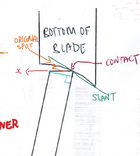
Yes, the slant, or more precisely the curve, on the bottom of the blade where it contacts the liner edge transfers force in a direction “normal” to the curved surface. Basically perpendicular to the curve, so in the case of your drawing through the 7 o’clock direction. This results in an X direction component like in your sketch (and a Y component too, but that’s vertical). The further the contact point moves to the right along the curve, the normal direction rotates more horizontal and the X component becomes greater. The reverse is also true.Yes, this is what I am hoping to talk, with reasoning.
For the point if the linelock travel more to the right, the spring becomes weaker, this is VALID. I took that into consideration. I actually bend the linelock out more so it put more pressure towards the right in the picture. Of cause that will make it harder to open the knife as the dot on the liner push harder on the hole on the blade that keep the blade from opening.
The fix is I round out the edge of the hole on the blade with a oval diamond drill bit( tip looks like an egg!!). With that, it open just as easy as original but now I put more pressure towards the right than the original knife.
As of the x y, here is my drawing from what I read your explanation.
Do you mean due to the slant on the bottom of the blade as shown in ORANGE, it generate the force in x direction as shown and push the linelock towards the left?
My response is as the linelock move to the left, it will travel to the ORIGINAL SPOT labeled in ORANGE. So that would be no difference as if the linelock was in the original position.
Remember i bend the linelock out more to put more pressure to prevent it from being pushed to the left as easy.
This is what I want to talk, we give our reason and see. I have an open mind, I don't insist on my way. I just want to talk it out like this. If you disagree, let me know.
Thanks for your time.
Remember too that the coefficient of static friction Is greater than that of sliding friction, so once it starts moving the force required to keep it moving is reduced. There is every reason to believe that once moving it will pass through the original position and continue, as long as there is a force maintained on the blade.
I missed the part where you bent the liner over further for more spring force, sorry about that.
What you said make sense, that the farther to the right, the more pressure in x direction to push the slidelock towards the left, that once it start moving, the sliding friction is smaller.Yes, the slant, or more precisely the curve, on the bottom of the blade where it contacts the liner edge transfers force in a direction “normal” to the curved surface. Basically perpendicular to the curve, so in the case of your drawing through the 7 o’clock direction. This results in an X direction component like in your sketch (and a Y component too, but that’s vertical). The further the contact point moves to the right along the curve, the normal direction rotates more horizontal and the X component becomes greater. The reverse is also true.
Remember too that the coefficient of static friction Is greater than that of sliding friction, so once it starts moving the force required to keep it moving is reduced. There is every reason to believe that once moving it will pass through the original position and continue, as long as there is a force maintained on the blade.
I missed the part where you bent the liner over further for more spring force, sorry about that.
Sounds like the best compromise is make it so it is very slightly in beyond the left edge of the blade, BUT not too far in like as shown in post #18. Just a little bit pass the left edge of the blade.
The bottom of the blade is curved, meaning on the left side of the curve, the x component is very small to start out with. I could swear on the far left side of the curve of the bottom, it's actually reverse the direction of x very slightly, That actually can help.
I have to look under the magnifying glass to tell.
This is a good discussion, this is exactly what I am looking for, things that make sense rather than "just follow what people do."
Thanks
Hi Blue SkyYes, the slant, or more precisely the curve, on the bottom of the blade where it contacts the liner edge transfers force in a direction “normal” to the curved surface. Basically perpendicular to the curve, so in the case of your drawing through the 7 o’clock direction. This results in an X direction component like in your sketch (and a Y component too, but that’s vertical). The further the contact point moves to the right along the curve, the normal direction rotates more horizontal and the X component becomes greater. The reverse is also true.
Remember too that the coefficient of static friction Is greater than that of sliding friction, so once it starts moving the force required to keep it moving is reduced. There is every reason to believe that once moving it will pass through the original position and continue, as long as there is a force maintained on the blade.
I missed the part where you bent the liner over further for more spring force, sorry about that.
After replying to you, I actually look at the bottom of my Steel Will Cutjack( I have 6 of them!!!). The bottom of the blades ( what do you call that?) are straight slant instead of curved. I attach a new drawing and with more questions.
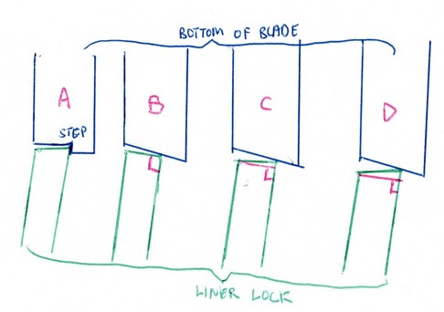
you can see the bottom is straight, just slanted at an angle.
I have another thing that I want to see your opinion.
As you can see in (B), (C), (D). I am looking at the angle to grind on the liner lock. Which is the best way? I like (D), but I think it will wear out faster.
After we talked, to me, the best is actually shown in (A) as I made a step at the bottom of the blade. the part where the line lock engage the blade, the surface of the blade is FLAT. There is NO x direction force as you described before. It's really not that hard to do.
Blue Sky
Gold Member
- Joined
- Jun 16, 2002
- Messages
- 3,582
You seem confident about modifying the angles, so you must have some good grinding skills. I’m unsure if changing the angle on the liner face will make the lock up more secure. It will create a more point-contact condition, but is that actually better? IDK. We can say a sharp edge is weaker though, and more prone to wear, in which case you will lose that precise fit more quickly. You may get a tighter lock for a shorter time.
Something to be concerned about is that if you make the lock up too secure, will it then start create problems with lock stick and/or difficult operation as others have suggested? Solving a problem by creating a different one has drawbacks.
The condition at A, if you were able to dial it in just right, would not slip easily under pressure if at all, but I bet it would also be difficult to disengage and close. There’s a fine balance here that would take a lot of experimentation to resolve.
At this point, I am talking more about the design and theory. Particular in condition (A), I don't have specialized tool to do that.
On the angle of the liner, I do it slowly and carefully on a diamond stone. I am quite good with my hands, not that it's good enough. I am trying to buy a few new liners if I can to experiment.
I know if the angle of the grind on the liner like in (D), it is slightly tighter, but definitely wear out faster. But in short term, even after I playing with it for days, I do NOT see it wear out.
At this point, it's really more talk. BUT I think it's fruitful to talk it out. I think if I want to do (A), I have to get a metal lathe. But that is a little too specialize for me as this is just a temporary interest. I do have more than just hand tools,
- Joined
- Dec 10, 2006
- Messages
- 6,000
I have not posted the below in a long, long while and some links might be broken, but here goes for those interested in learning more on this lock.
My framelock post
This is a compilation of resources and discussion on angles, lock interface, steel vs. ti etc. that I have compiled over the years.
Here are some comments from a very well and respected maker on the forums that has tested numerous locks. I will not post his name as this was a private conversation and let’s keep it that way.
"I've done some steel inserts in mine. The wear rates are not far off from titanium to steel. Both wear very well. Heat anodizing helps to form a deeper near ceramic hardness on the titanium since heating it by a torch anodizes the ti from the inside out as opposed to using a DC current which is from the outside in or the outside layer only. That ceramic hard oxide layer wears pretty well against even the hardest blades. If it didn't people would have stopped using ti a long time ago.
The real factors as I see it is impact strength not wear resistance. In my own testing for Kershaw and other companies that sent me product to beat the snot out of on their behalf I found that the steel frame knives held up better to sudden shock impacts like spine and overstrike whacking as opposed to the softer ti which could indent easier and deeper scarring the surfaces more. So to me this is the key factor behind it but there is a draw back since steel is less forgiving than titanium. Ti tends to gall or stick to itself and dissimilar metals and this sticking effect has been seen forever by makers as a real benefit.
Not to sound bad but you can be off some on contact angle and get by with it by using ti since it can make up for your short fallings here whereas steel would just slide right off the contact. Steel will demand the contacts be spot on and if they are not well, you'll see locks sliding off the contact toward release easier than ti when the contact angle is not right.
I've used inserts of steel in a couple folders I did a while back. To me having to do them the way I did they were more trouble than they were worth. Most of my folders give me very little trouble as it is. However, I am low key and not selling what is being marketed as a 'hard use' knife either. We'll see how long this lasts but it could be the beginnings of a trend in the hard use category if people start testing them and find they hold up better. It will depend on the steel used. I really fail to see much benefit if the steel they are using is just 410 stainless at 45 Rockwell. Ti is 39 Rockwell or so and although softer by quite a bit technically it wears at such a slow rate that in normal use most folks are not going to notice any diff or benefit to this insert at all. It’s just the guys beating on them that will pick up on it probably.
- Joined
- Dec 10, 2006
- Messages
- 6,000
Now that goes to another issue. What happens when the insert dislodges or falls out? The screws will have to be very secure for some of these guys beating on them and if they think the knife is supposed to take it they will do that. Again time will tell. My thoughts are that overall there are some benefits from the stand point of repairs.
It’s much easier to replace an insert to refresh a lock that has worked its way all the way across the contact. This beats the hell out of making a whole new lock or peening the contact like Emerson, Kershaw and many other companies do to repair theirs. Don't get me wrong that’s an old cutler trick as old as the liner lock itself and it works. Heck many makers do it as a part of the process along with heat treating because they believe peening compresses the molecules making it denser so it wears better.
The point is that is not as precise as people like to be whereas a new insert would be, well, new and just like it was before theoretically. It may even be something the user can do themselves in the field or at home. We'll just have to see how this develops. "
eening the contact is a technique used by cutlers to 'refresh' the actual physical contact area on the lock where it connects to and wears against the blade in use. Since the lock is technically supposed to connect and support the blade at the bottom of the lock at the point far enough away from the mid line of the pivot barrel or pin to prevent 'blade roll', (bottom being the area many refer to as the top since its up by the thumb grooves where one depresses the lock to release and free up the blade to close it. Think bottom of the blade when opened and that is technically the bottom of the knife and the where the edge runs with the spine of the blade when opened being at the bottom running along the full length of the folder)
So again since the lock connects at the bottom you have a triad or three points to support the blade when opened. The stop, the pivot in the middle and the lock. If the blade connected to the lock more in the middle or at the top of the lock down where the detent is on most then you would experience blade roll. This is when you have vertical type play but what happens is the blade actually rolls on the lock because the lock connects in the wrong place.
The lock should also be flat not angled at a pitch like the contact is on the blade. Some makers make them and the blade is not quite right so they adjust the lock to fit the blade instead of the blade to fit the lock. This is incorrect and it can cause a 'stepped' or angled pitch to be formed on the lock and that in conjunction with a pitch on the blade is a sure fire way to lead to lock defeats.
When a lock wears and works its way across the tang to the opposite side liner or when it develops blade play many times the maker or the manufacturer will correct this not by bumping up the size of the stop pin but by peening the contact area. This again if you picture it is the area showing signs of wear marks on the lock itself and it should be somewhere on the bottom third of the lock far enough from the mid line of the pivot to make a rock solid contact for no play in the blade. Peening means a ball peen hammer and a 3/32 flat end punch placed precisely at a the area just to the left of the contact on a right handed knife. You swing the hammer hitting the punch so it physically 'squishes' out the contact more toward the blade. When done this creates a little 'bubble' sticking out just a few thousandths of an inch and it refreshes the contact as well as compresses the material. This can be done on steel, ti or brass locks and requires different touches or pressures to do it right. It’s been done on compression locks and lock backs also to peen the usually softer area of the rocker arm just a micron or two to adjust the lock for fit before they ship it out the door.
Anodized ti is usually surface only. Heating with a torch usually brings the ti lock contact up to a straw colour or at the least a cherry red orange colour. Letting it cool on its own and repeating this three times builds up quite a bit of anodizing that at times can be resistant to even bead blasting it off and it can harden the metal to the point that it is much more wear resistant in that spot that was heated. Most are done and then blasted afterwards cleaning off the surface that is seen. Others simply don't treat it knowing that titanium is technically a 'self healing' metal that creates an oxide layer on its own as soon as fresh ti is exposed to oxygen. This is true by the way and why ti is resistant to all kinds of corrosion. It’s that oxide layer that forms a barrier between the ti and the atmosphere sealing it off that makes it so resistant to it. Heat and electric current simply stack on layers of this seal and the light refracting off those multi layers is why we see colours. You actually would have to read some of the tech manuals on that to get the full jist. I'll stick with a nut shell description.
Correction. Steel would probably have been dinged also just not as bad and this depends as you said earlier on type of steel, how hard it was set at and so on. Steel as I said requires that things be just so. I repair a lot of knives and most are liner type locks of the thinner type. These wear and indent and even in steel. They also of steel tend to be easier to find fault in contact angles. For example you see a few knives with steep pitch angle contacts 12 degrees or more and to try this with steel will surely cause the locks to defeat with a sharp tap to the spine. Most steel locks need a pitch of 7 to 8 degrees max to work. 10 or above is really pushing it and even Spyderco walks that fine line at times as I see plenty of Military folders with locks that slide toward release back to the flatter area on the blade contact. This with simple spine pressure from my hands so there is no telling how that would go for the user if it was a sharp blow to the spine. "
- Joined
- Dec 10, 2006
- Messages
- 6,000
"Correction:
Peening the contact is a technique used by cutlers to 'refresh' the actual physical contact area on the lock where it connects to and wears against the blade in use. Since the lock is technically supposed to connect and support the blade at the bottom of the lock at the point far enough away from the mid line of the pivot barrel or pin to prevent 'blade roll', (bottom being the area many refer to as the top since its up by the thumb grooves where one depresses the lock to release and free up the blade to close it. Think bottom of the blade when opened and that is technically the bottom of the knife and the where the edge runs with the spine of the blade when opened being at the (insert TOP not bottom as I said) running along the full length of the folder) Even I get confused. Lay people often mean top when they mean bottom and bottom when they mean top because these two points are confused.
The point is the lock should connect at the bottom third of the lock and nowhere near the pivot mid line or top. "
And here are some other comments from me and my opinion.
For those like me that like the theory
A recent few posts I did regarding frame locks, but many of the same principles apply to liner locks geometry.
"There are a few things I want to cover, based on my talking with custom makers and reading Bob Terzuola's book: The Tactical Folding Knife (hereafter BT), where he explains in detail the aspects of a good liner lock and the same principles are applied to framelocks.
Three points of contact:
1. Stop pin
2. Pivot pin
3. Interface between blade and spring (ie, lockface/lock engagement area hereafter referred to LF) Spring is also the liner lock, framelock.
This forms a triangle.
Now, the LF is the area let’s focus on first.
BT. refers to the angle of the lock face to be between 7.5 and 8.5 degrees. Les then 5 degrees and the spring will jam. More than 10 degrees and the spring will start slipping off the LF.
Now the start of a radius lock face, the maximum therefore cannot exceed 10 degrees or else the lock will start slipping when the lock wears to that point. As mentioned as lock rock in the video when referring to the Strider ()
Now.
Do not thing the angle plays the only role in the lock slipping. The finished LF can have a rough spot, not be polished enough, the spring's interface between the LF can also play a role.
Let us examine this from the Emerson website.
http://emersonknives.com/blog/emerson-knife-anatomy/
If the LF connected to the spring more in the middle or at the top of the spring where the detent is on most (point nr 3 closer to the pivot pin nr 2) then you would experience blade roll. This is when you have vertical type play but what happens is the blade actually rolls on the spring because the spring connects in the wrong place with the LF.
The picture shows the extremes of the different designs; you can have a lock that engages more than the bottom 0.90-.125" of the spring. Chris Reeve has proven this, but, you can also have a knife that engages only on that bottom 0.90" (point of contact in the picture)
Not every lock is the same. The basic ingredients are the same, but the final application is what the maker chooses. This can be seen even with Spyderco difference between the Military and the Gayle Bradly.
Now that is just the geometry of the lock.
The spring itself if it is Titanium can be heat treated or carbonized. Strider and Hinderer do the latter. This helps tremendously with wear on titanium and if done right will last you a life time. CRK and a few custom makers that I have do Heat Treating of the lock. Wear is about nun and equal to (if) steel was used.
HOWEVER. Titanium is NOT PERFECT and it can have flaws in it when received from the supplier. EVEN aerospace titanium (grade 5 titanium). These flaws only become apparent when it is used and is sometimes not even noticeable until it begins to form a problem. This is where a good warranty comes into play.
Steel used as a liner is not always the answer as well. Different steel interfaces can result in slipping. Steel on steel requires a lot of research to find what can be used and heat treated as a spring and still provide excellent wear resistance and safety.
Finally, lockup percentage is a strange thing and depends on the final user. I prefer later lockup as it usually means less chance of slipping off the LF.
I hope this helped you in some way."
At the end, if you either use Ti or Steel, the LF geometry is key.
I have Ti lock custom that I have flicked vigorously, the maker asked me to test the lock face.
BT also writes in his book there is no significance between steel and Ti if done right. A Sebenza will wear for a while and then stop. Most quality locks do this. Chris Reeve also wants a later lockup as
- Joined
- Dec 10, 2006
- Messages
- 6,000
he feels it provides a safer lock and less chance of slipping. I tend to agree. Besides. If any quality product wears out so fast, they should cover it under warranty.
I have seen a 18 year old Sebenza. No issues. I have a Military with the steel insert. No issues. Both locks apply different end results, but the basics are the same resulting in great locks that can last you a live time.
BT also feels that the strength to weight ratio of Titanium is excellent compared to steel.
Some imagery
Comments from well-known custom maker Des Horn
Now, there is also been some good testing and evaluation done by Kyle Harris (cKc Knives) from new Zealand discussing blade play vs lock security. In short, though we think blade play is bad, making a truly dependable lock in the framelock/linerlock conversion requires some blade play.
Have a look at these videos:
www.youtube.com/watch?v=M2cZQv5cIqQ
- Joined
- Dec 10, 2006
- Messages
- 6,000
You can see from the videos that even with blade play a lock can still be very secure, very reliable and would require the entire lock to self-destruct in order to disengage.
Real interesting comments from Gavkoo on the folder of Kyle and what makers such as Bob Terzuola said about bladeplay being a thread for the specific market, yet there is nothing wrong with the design.
People presume that blade play is bad, but not for a reliable lock. I would venture and say that the Victorinox soldier will only fail if there is a catastrophic failure of nature, same as the Tri-Ad. Under static load, the soldier might even surprise the best of us.
Interesting thing on how durable a liner can be:
I hope this can be useful and educational to some. I know I went a bit of topic... from steel vs Ti, but you have to look at it as a whole in my opinion
One of the best ways I have seen to test a liner/framelock for any issues is to do the following (this was posted back in 2007):

Umnumzaan design:
The ceramic ball lockup is supposed to look late, but in in reality is not.
")
- Joined
- Dec 10, 2006
- Messages
- 6,000
Added from:
http://www.knife-expert.com/liners.txt
THE LINERLOCK -- RIGHT FROM THE SOURCE
Michael Walker's invention and development of the LinerlockTM
by Bernard Levine (c)1997 - for Knives Illustrated
The "Linerlock" knife is now so familiar that it is easy to
forget that both the knife and the name are relatively recent
inventions. Michael Walker made the first modern Linerlock in
1980, and he registered the name Linerlock as a trademark in
1989. Since the mid 1980s, dozens of hand knifemakers and factory
knife manufacturers have made locking liner type knives inspired
by Walker's designs, although very few of them fully understand
either the advantages or the limitations of this mechanism. The
best way to understand the Linerlock is to look back at how
Walker developed it.
THE EARLY DAYS
Mike Walker began to make knives early in 1980. One of his
first customers was a collector and dealer in Red River, New
Mexico, named Don Buchanan. Mike made ten fixed blade knives for
Buchanan. Don asked Mike for sheaths to go with these knives.
Mike made those leather scabbards reluctantly, then announced
that he hated making sheaths. So Don said, "Make folders."
Mike did. He made slip joints. He made lockbacks like the
factory folding hunters then on the market. He made mid-locks
with mechanisms copied from antique folders. But he was not
satisfied with any of these. Walker envisioned an improved folder
that would do away with what he saw as the many limitations of
conventional lockbacks.
First, he would design a knife that the user could open and
close safely and easily with one hand, without having to change
one's grip, or rotate the knife in one's hand.
Second, his new knife would do away with the sharp "back
square" of the conventional pocketknife blade. When a
conventional blade is closed, its back corner sticks out, and can
snag the user's clothing. In some folders the back square is
enclosed by extended bolsters, but this can compromise the shape
of the handle. Mike envisioned changing the basic geometry of the
folder, in order to eliminate the problem entirely.
Third, and most subtle, his knife would be self-adjusting
for wear. Other innovative folders of this period, notably the
Paul knife by Paul Poehlmann (patented 1976), were very strong
and very sleek, but they required careful adjustment of set
screws to keep their blades from working loose.
THE LOCKING LINER
Mike was familiar with the old locking liner design patented
by Watson & Chadwick in 1906 for Cattaraugus. Used first on
traditional folding hunters, this mechanism became standard on
electricians' pocketknives, and was also used on Cub Scout
knives. In this design, the liner projects above the handle, and
it is split lengthwise, alongside the pivot pin. The side of its
narrow tip engages the front edge of the tang when the locked
blade is open.
Mike noted that only a thin extension of the liner could be
used as the lock in the Watson & Chadwick design. This was
because most of the liner had to engage the pivot pin, in order
to hold the knife together against the tension of the backspring.
The result is that this type of lock is inherently weak.
Mike went back to first principles. He realized that if
spring tension and lock-up could be provided by a liner alone, he
would be able to dispense with the backspring entirely. With the
back spring gone, he could then have the end of the liner cut-out
engage the bottom end of the tang, making for a much stronger and
more positive lock. Indeed it would be nearly as strong as the
old Marble's Safety folder (patented in 1902), while dispensing
with that knife's long, awkward, and fragile fold-up extension
guard (the folded guard serves as that knife's lock when the
blade is opened).
STRONG AND SECURE
As it worked out, Mike had not anticipated just how strong
his new lock would be. About 1984 I helped to run side-by-side
destruction tests of all the types of locking folders available
at that time. Each test involved securing the handle of the knife
without blocking the movement of its blade or spring; then
sliding a one-foot pipe over the open blade (which was oriented
edge downward), to serve as a lever-arm; and finally hanging
weights from the free end of the pipe until the lock failed.
Name-brand conventional factory lockbacks failed at between
5 and 7 foot pounds (except for one that failed with just the
weight of the pipe). A Paul button-lock knife proved to be more
than twice as strong as the best of the conventional lockbacks.
But a Walker Linerlock was nearly four times as strong as the
lockbacks. What's more, when Walker's Locker did finally fail, it
failed in the open position. Instead of closing suddenly upon
failure, as all the other knives did, it seized up and became a
"fixed" blade.
SELF-ADJUSTMENT
This strength turned out to be a fringe benefit of Walker's
self-adjusting design. He based this design upon the simplest of
all mechanisms, the inclined plane, or wedge. The end of the tang
is slightly beveled. The end of the liner is not (although it can
be, as long as the angles do not match). Both parts must be hard.
When the blade is opened all the way, the liner passes the inner
edge of the tang, but it is stopped before it passes the outer
edge. The liner's leading edge bears on the beveled end of the
tang. If the pivot joint loosens over time, the point of
engagement of the lock-up moves further along the bevel, so it
continues to lock up tight.
In the destruction test, when we applied an extreme load to
the blade of Walker's Linerlock, the free end of the locking
liner moved all the way past the end of the tang, and wedged
itself between the blade and the fixed liner. Mike was later able
to disassemble and repair this test knife, and today it is
(almost) as good as new.
In his first Linerlocks (he was not calling them this yet),
Walker made the liners out of spring-tempered 440-C blade steel
(he did, and still does, his own heat treating). The lock-ups
were not yet the full width of the tang -- Michael changed this
after the destruction tests, to make his knives even stronger.
The thick 440-C liners of those early versions applied so
much spring pressure to the blades that no other mechanism was
required to retain the blades in the closed position. But when
Mike began to experiment with lighter gauge liners, he realized
that a separate element would be needed to perform this function,
which is performed by the backspring in conventional knives. In
1984 Mike began to incorporate a ball detent in the frames of his
Linerlocks, allowing the liner to be dedicated totally to lock-up
in the open position, while the ball detent held the folded blade
closed.
TITANIUM
These new lighter gauge liners were made out of titanium
alloy. Titanium has many features that make it especially
suitable for this application.
- Titanium has a high strength to weight ratio.
- Titanium has superb spring retention qualities, without the
necessity of any heat treatment. A titanium spring will recover
from a severe load that would permanently deform a steel spring
of the same cross-section.
- Titanium galls to other metals -- it seizes to them, rather than
slipping past them, when they are rubbed together under tension.
This makes titanium useless for moving parts, but ideal for parts
that are meant to seize, such as the end of a liner engaging the
end of the tang of a folding knife blade.
- Titanium can be electrolytically toned to a wide range of
attractive colors. Michael and Patricia Walker pioneered the
application of this technique to knives. In fact Patricia Walker
was the first artist to engrave and anodize titanium, both on her
husband's knives, and on her own jewelry and artwork.
ADVANTAGES AND LIMITATIONS
Walker's Linerlock mechanism is flexible and forgiving in
many ways. In the 1980s Mike would go to shows with a box full of
unfinished blades that he had ground freehand in all sorts of
- Joined
- Dec 10, 2006
- Messages
- 6,000
shapes. Customers would pick out ones they liked, and Mike would
then make knives around these blades, without any need for the
precise patterns that burden the makers of conventional lockbacks
and slipjoints.
However, one aspect of the Linerlock is not forgiving at
all. This is the bevel at the end of the tang, on which the end
of the locking liner bears. If this angle is too acute, the liner
will slip and the lock will fail. If the angle is too obtuse, the
liner will stick, and the blade will be difficult or impossible
to close.
Mike emphasizes that there is no single correct angle for
this bevel, as some writers have mistakenly claimed. Rather it
must be determined for each knife. The optimal angle is a
function of the blade and liner materials, of the spring tension
of the liner, and most important of all of the overall length of
the knife. The free end of the liner moves in an arc of a circle,
and the length of the knife determines the radius of this circle.
LINERLOCKS TODAY
Mike Walker rarely makes Linerlocks any more. He has
licensed the name, and various aspects of the mechanism
(including the patented safety latches recently developed jointly
by Walker and Ron Lake), to a few other makers and manufacturers.
On his own current knives he uses some of the dozens of other
locking mechanisms that he has invented over the years.
Mike is flattered that so many makers and manufacturers use
his invention, though he is disappointed that most of them fail
to grasp all the subtleties of the Linerlock mechanism. Because
of this, most of their knives lack the strength and smoothness of
Walker's own.
And Mike is angry at certain pompous Johnny-come-lately
makers who attempt to claim credit for his inventions and his
designs. One shameless maker is today receiving royalties for a
design that Walker created two years before that particular maker
assembled his first knife. But Mike never patented his original
mechanism or his early designs, so this sort of copying is now
water over the dam.
However Walker's trademark rights are another story. Mike
lets his lawyers deal with any makers or manufacturers who have
the temerity to use his "Linerlock" trademark without his formal
written permission.
- Joined
- Dec 10, 2006
- Messages
- 6,000
Some good work was done here to showcase the influence of lockbar cutout placement, however, it should be noted many knife makers etc have discussed this with engineers and in a knife the difference is negligible. If we were building massive structures then the case would be very different.
Added 2015
http://jgcustomknives.com/guthrie-tungsten-insert/
GTi LOCK:
The GTI lock stands for GUTHRIE TUNGSTEN INSERT. It features a Tungsten Carbide Insert fitted into the lock face of the R.I.L (Reeve Integral Lock) Tungsten Carbide is incredibly hard, achieving 90HRC on the Rockwell scale. This high hardness reduces lock wear greatly. A knife fitted with the GTI lock is guaranteed against any lock wear that will induce lock rock or vertical blade play.
LOCK TRANSITION:
This term refers to the maturing of the lock as wear takes place. The very small amount of lock wear (which now moves to the hardened blade) that could occur with the GTI lock has proved to be beneficial. It does not have the same detrimental effects as the lock bar wearing. Slope force is the sideways force the lock experiences when the blade is pressed against the lock. Increasing the incline on the blade lock face, increases Slope force. Increasing Slope force decreases reliability as the greater force wants to push out the lock bar, resulting in lock failure or lock slip. When a lock bar wears, it wears to the same incline it is being pressed against. In this case the incline of the blade. Slope force now increases and reliability decreases. With the GTI lock, the opposite effect happens. The Tungsten Carbide wears the blade to a shallower incline, which decreases Slope force, resulting in more reliability as time goes by.
Due to the nature of this exceptionally hard lock, it is not guaranteed against any spine whacking. Used as a normal cutting tool, this knife should never run out of lock life.
ROCKWELL COMPARISON:
Stainless Steel 25-34 HRC
Titanium 36 HRC
Hardened SS 58-62 HRC
Ceramic (Silicone Nitrate) 80 HRC
Tungsten Carbide 90 HRC

- Joined
- Dec 10, 2006
- Messages
- 6,000
Updated 2018, February.
Additional to the above based on Bob Terzuola’s and Michael Walker’s work Andre Thorburn has adapted a radius lockface, however slightly modifies it through manual adjustment to stop any lock stick from occurring. It is difficult to explain the process and I do not have permission from him to disclose additional information, but it proved once again for me, that geometry is key, above all else.
Happy reading
Do you have any picture related to the article linked?
https://www.knife-expert.com/liners.txt
It's very hard to understand just by reading.
Thanks
- Joined
- Dec 10, 2006
- Messages
- 6,000
Unfortunately not.Do you have any picture related to the article linked?
https://www.knife-expert.com/liners.txt
It's very hard to understand just by reading.
Thanks
I would recommend purchasing R. Terzoula’s book:
The Tactical Folding Knife: A Study of the Anatomy and Construction of the Liner-Locked Folder
- Status
- Not open for further replies.