What is your dream forging press?

adammichael said:
I always call someone Mr. when i respect there work and opinions. You know what i mean Mike? Sorry, I meant Mr. Fitzgerald:D

There is a strong need here for an icon with a little guy with a smiley face and a gesture..... ;)

Go buy a pump and and controller....... I'm anxious. :p
 
I can't sleep... a spring fuller is used for fullering (sorry, not being a jerk, I'm about to explain) fullering is the process of using something that resmbles a miniature die to produce a specific indention in the material being forged.

The term spring fuller is often used interchangeably with the term spring swage, so I will describe what both terms cover, since theris some confusion over which is which.

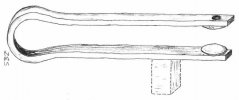
Spring fuller (or swage) implies that there are top and bottom fullers attached with a long handle, that's jointed with a large curve allowing it to spring. spring fullers can be used to make all kinds of fun shapes, leaves, balls, wood grain pattern, etc. as well as swaging stock down to a specific size, or just plain fullering, if you have a plain fuller at 90º with a bar, you put a neck in the bar, if you use flat bar, and fuller lengthwise, you can put a "fuller" or blood grove in something, but it's sometimes hard to forge it straight, and keep it pretty when you grind it.

There are all kinds of spring fullers that have been made, they can also be used for texturing like the one I've included a picture of.

attachment.php


The one pictured is designed to fit in the hardy hole of an anvil, and be hand hammered (not my picture)

Having said all that, I think of spring fullers as tools, are more useful in power hammers, simply because you can turn the work as you forge between relatively light strokes compared to what a press produces. it's also possible that Bowie is talking about something else entirely, and using a name for it that implies something different to me. (remember, I'm a blacksmith)

Tony
 

Attachments

  • spring fuller sm.jpg
    spring fuller sm.jpg
    19.6 KB · Views: 207
That’s a great looking press and it not going to move I think you stated you wanted more than 30 tons –I think it will hold up great ,but you already know that .

And its my favorite color ( viper red )

Fullers are as has been mentioned are for textures and forms I was thinking of placing aa hardy hole off to the side of the bottom die holders to hold spring fullers, some patterns-- textures on steel and it would be appealing to blacksmiths as well .has you told leaves nuts vines they could be made by the press owner as he see fit and I don’t think the hole in the steel plate will cause a weak point
Bowie Getherdone pressing is fun
 
Mike
thank you for that explanation. I do believe this is (well) over built as you said.
and true the welds are the key here,,

I took some things out of context to push my point.. mostly in a what if situation that you had covered in this being over built in the first place.
what I was attempting, was, if it could be over powered what would happen
to the lower parts
and yes other things sure would let loose first.. :eek:

I think as you too if you do bring the one tube up under the plate that would be great. bringing in the side welds.
and as these are drops why not put two there :D
while thinking about it , the point of the inside tubes being at that length could be as an added benefit if there were
any lower tube deflection, this would cause a side tube deflection lessening the chances of a weld brake
was that what you were taking about other benefits?
well something like that .
like I said I can't type what I'd like to say.. so I'll stop.
I hope you all had a great time today I did, I think my youngest boy is showing me up on skies now.


one problem though with the press now..,,, :rolleyes:
you got the feet on the wrong sides ;)

come on guys..

that was a,,,, I'm kidding funny:D
 
Dan Gray said:
Mike
thank you for that explanation. I do believe this is (well) over built as you said.
and true the welds are the key here,,

I took some things out of context to push my point.. mostly in a what if situation that you had covered in this being over built in the first place.
what I was attempting, was, if it could be over powered what would happen
to the lower parts
and yes other things sure would let loose first.. :eek:

I think as you too if you do bring the one tube up under the plate that would be great. bringing in the side welds.
and as these are drops why not put two there :D
while thinking about it , the point of the inside tubes being at that length could be as an added benefit if there were
any lower tube deflection, this would cause a side tube deflection lessening the chances of a weld brake
was that what you were taking about other benefits?
well something like that .
like I said I can't type what I'd like to say.. so I'll stop.
I hope you all had a great time today I did, I think my youngest boy is showing me up on skies now.


one problem though with the press now..,,, :rolleyes:
you got the feet on the wrong sides ;)

come on guys..

that was a,,,, I'm kidding funny:D
Mr. Grey, the shelves for the dies were added as an after thought but they do offer some added stiffness to the bottom assembly. Its always a good thing when 1 part can serve multiple functions.

As far as the legs being on the wrong side, your correct. I designed it with the short legs out the front and no lip on the die storage shelves but the guy who put the shelves in for me misread the print and put them in backwards. I could either cut the front lip off of all the shelves and weld a back lip on them so the dies dont slid off the back or make the front the back and the back the front. I took the easy way out on that one.

Now were back to the guide system. Anyone have any additional thought on what i have drawn up sp far?
 
fitzo said:
What happens if, instead of having the clevis "bracket" a central potential "pivot point" upright on the "top plate", one instead has two upright pieces with the clevis in between them. That would separate the stress farther outwards but I don't know if clevises (clevii??) are meant to operate like that. Perhaps the gussets in the drawing do exactly that. Just thinking out loud....
Good point Mr. Fitzgerald. I think the gussets that are already there serve that purpose to some extent but maybe some additional gusset on the front and the back of the plate for the bottom clevis would help stiffen it up in that direction. Do you all think the binding is going to occur from left to right if the billet is off center or front to back if the billet is off center? If you notice the existing gussets on the left and right of the lower clevis plate extend all the way to the ends of the dies.
 
Mr. Kanter, I was thinking of some weird system with a long pin traversing two outboard upright pieces as a way to provide some lateral stability. Later thinking got even sillier when I conceived having both the "outriggers" and the center hole but also having the holes carefully drilled so that the center was just a smidge lower towards the die plate and thus loading the outboard holes first.

Now, Mike, I don't know if that explanation made a bit of sense whatsoever let alone the concept probably being whacky. Consider the source.... ;)
 
adammichael said:
Mr. Grey, the shelves for the dies were added as an after thought but they do offer some added stiffness to the bottom assembly. Its always a good thing when 1 part can serve multiple functions.

As far as the legs being on the wrong side, your correct. I designed it with the short legs out the front and no lip on the die storage shelves but the guy who put the shelves in for me misread the print and put them in backwards. I could either cut the front lip off of all the shelves and weld a back lip on them so the dies dont slid off the back or make the front the back and the back the front. I took the easy way out on that one.

Now were back to the guide system. Anyone have any additional thought on what i have drawn up sp far?
and I thought the picture was taken of the back side :)

if the tubes were a bit longer farther apart, bushed, sealed and grease-able.
that would stop a lot of binding ,, struts on cars are very small but work for many miles ,
though the side pressure is not all that great but nothing to sneeze at
 
fitzo said:
Mr. Kanter, I was thinking of some weird system with a long pin traversing two outboard upright pieces as a way to provide some lateral stability. Later thinking got even sillier when I conceived having both the "outriggers" and the center hole but also having the holes carefully drilled so that the center was just a smidge lower towards the die plate and thus loading the outboard holes first.

Now, Mike, I don't know if that explanation made a bit of sense whatsoever let alone the concept probably being whacky. Consider the source.... ;)
I think I know what your saying and i dont think any of it is silly. If it gets everyone thinking in a different direction, who knows what we will come up with. Its called "thinking outside the box"

My initial thoughts were right along the same line as what you are saying and it evolved, in my head, to what i have shown. If you can draw a sketch on a piece of paper and post it that would go along way to determining if we are on the same page. If we arent maybe we will come up with something completly different because of our little exchange.
 
Dan Gray said:
and I thought the picture was taken of the back side :)

if the tubes were a bit longer farther apart, bushed, sealed and grease-able.
that would stop a lot of binding ,, struts on cars are very small but work for many miles ,
though the side pressure is not all that great but nothing to sneeze at
In my mind, I am seeing the squish of the billet being about 1/4" to 1/2" max. The guide collar is 4" long. That means that the squish is only 4% to 8% of the collars total length. I believe that is plenty of support to keep the top die and ram from binding. The lateral force on the 2" solid round bar will be concentrated near the bottom 3rd of the bar near the bolts and the welds. I dont think the round bar will be moving at all. The collars are gusseted on 3 sides so I believe the week point will be the outboard side of the collars. Longer or thicker collars would be stronger. Remember, I was hoping this design would be strong enough to press off center of the cylinder ram.

What am i not seeing?
 
Michael, one other thing while it's in my head. I know you're going to put zercs (sp?) on the slides. Think there'll be any worry about flakes of slag sticking to the greased shaft and galling?

I'll draw a little something up and scan it in manana about my comment. I'm a bit thinking, though, that this may be more like inside the rubber room than outside the box.... ;)
 
fitzo said:
Michael, one other thing while it's in my head. I know you're going to put zercs (sp?) on the slides. Think there'll be any worry about flakes of slag sticking to the greased shaft and galling?

I'll draw a little something up and scan it in manana about my comment. I'm a bit thinking, though, that this may be more like inside the rubber room than outside the box.... ;)
You have been more help to me than you realize, Mike, so im right there in that rubber room with you.

Does most of the slag happen when the squish happens or is it poping and spitting when the billet is positiond on the dies?
 
adammichael said:
In my mind, I am seeing the squish of the billet being about 1/4" to 1/2" max.

I'm thinking in terms of a stacked Damascus billet. more possible slippage in side pressure
and teetering of the center point..
I'm not sure what the first compression would be on a (say) 30 layer stack
at say 30 - 35 ton or more.
 
Modified version of the ram guide. I stiffened up the collars with extra bracing.

What do you think?
 
Mike, thanks for the kind compliment.

Personally, I think stiffening the upper plate assembly and slides and eliminating as much side-to-side cant as possible will only improve the functioning of your multi-dies.

As far as the slag, I find that it pops as I squish. The flux has chemically complexed the oxides that formed after fresh metal was exposed on the previous trip to the press and now forms a sheath around the billet. It is far less flexible than the hot steel itself. Thus, when I apply pressure it causes that rigid oxide complex to first crack and split and then shatter, scatterring the slag.
 
Michael - do you have access to stress-coloring/shading software? (sorry, can't remember what it's called)

I remember visiting a structural engineer's office once and seeing some 3D-modeled load visualizations. Reminded me of some polarized plastic stuff I played with in college that would shade when stressed....those stress lines helped us pin-point areas susceptible to failure.

Sure would be neat to simulate the press under 80% load to see where the stress points are.

Any of this sound familiar? I'll do some looking online...maybe there's a freeware version out there...
 
Daniel Koster said:
Michael - do you have access to stress-coloring/shading software? (sorry, can't remember what it's called)

I remember visiting a structural engineer's office once and seeing some 3D-modeled load visualizations. Reminded me of some polarized plastic stuff I played with in college that would shade when stressed....those stress lines helped us pin-point areas susceptible to failure.

Sure would be neat to simulate the press under 80% load to see where the stress points are.

Any of this sound familiar? I'll do some looking online...maybe there's a freeware version out there...
I believe you are refering to FEA software. ( Finite Element Analysis ) I do not have access to that where i am currently working but I used it at my previous place of employment. It is amazing what you can see with it.

Here is a pic of the ram closed to clarify what i am thinking.
 
that's getting complicated..
Mike
is there enough strength in the (what I call) pad-eyes
on the other end of the piston?
if there is
you could just turn the piston end for end..
using the cly end plate and pads for the strength and stabilization you need?
the length of the body will give a lot of leverage to the piston rod if on the other end.

then you can remove that stuff and the piston rod would be up out of the way from slag also..

the hoses would move more but 6 wire would take care of that..

edited to add
forgot to add
then to guild the die a guild pin set up through the die plate should do it.
 
Back
Top